25
125
b
a
d
fe
b
bc
h
i
m
g
c e
a
7511131
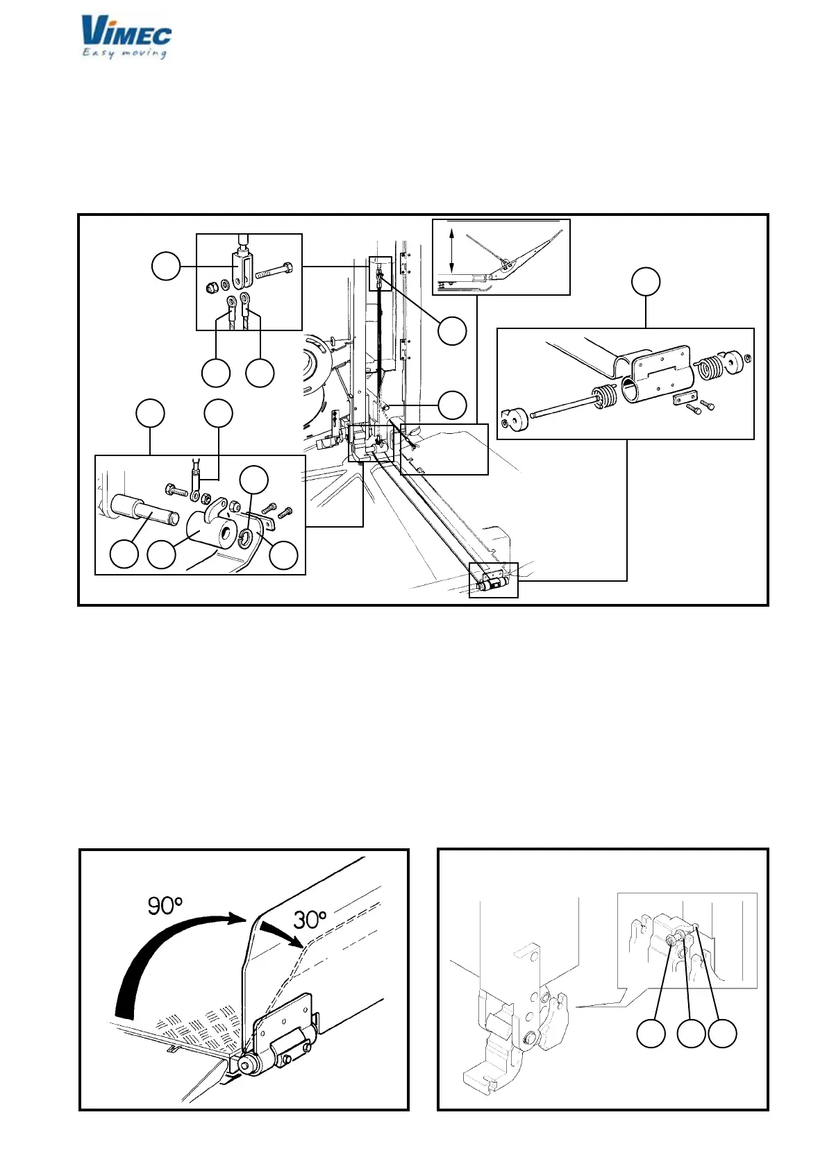
c) Fit the platform, keeping it vertical and turning it
through 90° as shown in (Fig. 22).
d) Fix the platform to the frame using the TSPCE M8
at-head screws (Fig. 22/a).
e) Plug in the connector j4 (Fig. 23).
f) Connect the side (Fig. 24/f) and front (Fig. 24/e)
guard board operating cables to the fork (Fig. 24/b).
- Tighten with nut and screw.
- Insert the eccentric (Fig. 24/h) with handling belt (Fig.
24/g), front guard board on the special pin (Fig. 24/i)
and block with seeger (Fig. 24/m).
B.R.: Fix the cable (Fig. 24/f) already present on the
side bar guard board with special screws.
Proceed to check the proper working of the front access
guard board:
- Check the angle between the guard board (in working
position) and the footboard is 90° (Fig. 25).
- Check the front access micro guard board intervenes
with a maximum rotation of 30° of the same guard board
with respect to the working position as in Fig. 25.
- If the guards are not opened or closed correctly,
adjust to the specied position using the register fork
(Fig. 21/b).
- Fix the cable eye (Fig. 24/e) to the eccentric (Fig.
24/h) by screw, nut and locknut leaving the necessary
clearance for the rotation of the eye itself.
g) Replace the top plate on the platform using the
relative xing screws.
h) Remove the wedge and the plastic clamp (Fig.
21/c/d) used to keep the platform horizontal during the
adjustments from the platform supports.
i) Tighten the dowel, the nut and the locknut (Fig.
26/a,b,c) with a driving torque of 4 daN ± 0.1.
l) Check that the clutch group is engaged.
FIG.24
FIG.25 FIG.26
7512131