Operators guide
13
Maximum and minimum payloads that can be balanced are dependent on the weight of the
camera system and on the centre of gravity (C of G) height. The counterbalance chart (Fig. 5)
shows the range of payloads and C of G heights that can be maintained in balance. The shaded
area on the chart shows the payload/C of G combinations that can be maintained in balance.
Where a payload/C of G combination falls outside of those shaded areas it will be necessary to
increase or decrease the weight or the C of G height—if possible—to enable the head to balance
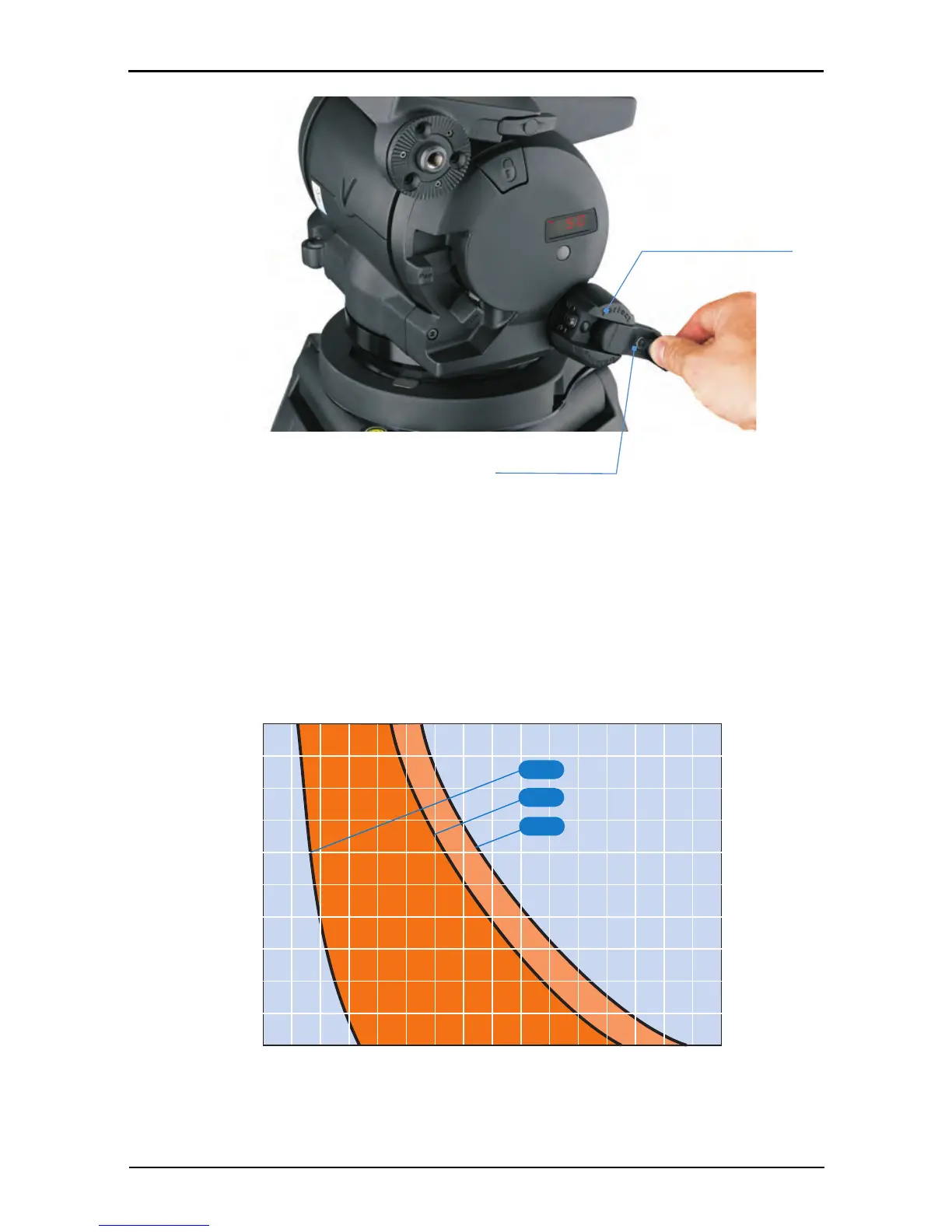
the load. A digital numeric display [3] indicates the setting of the counterbalance mechanism.
Fig. 4 Perfect Balance knob with fold-out handle
Fig. 5 Counterbalance chart