Do you have a question about the Viqua Trojanuvmax IHS12-D4 and is the answer not in the manual?
Details grounding requirements and risks for electrical shock.
Explains the need for GFCI protection for electric shock prevention.
Guidelines for using extension cords safely with the system.
Lists essential safety precautions for operating the UV system.
Lists operating pressure, temperature, humidity, hardness, iron, and UVT.
Details maximum rated flow rates at different UV doses.
Specifies voltage, frequency, current, and power consumption.
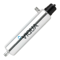
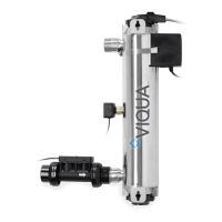
Lists UV chamber material, inlet/outlet, and lamp service life.
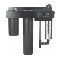
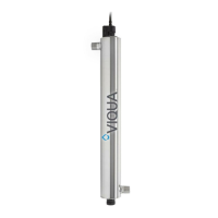
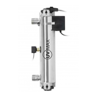
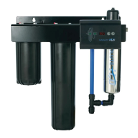
Lists and identifies key components like power supply, cords, and bracket.
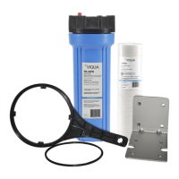
Lists lamps, sleeves, filters, wrenches, and other parts.
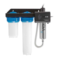
Illustrates the system layout and labels key components and connections.
Determine indoor location, ensuring clearance for lamp/sleeve removal.
Mount the system to the wall using lag bolts and bracket.
Make necessary plumbing connections as per drawings.
Slide the power supply onto the mounting bracket.
Slide the reference card behind the power supply.
Ensure outlet is protected by a Ground Fault Circuit Interrupter (GFCI).
Install sleeve bolt with o-rings and screw lamp into sleeve hand-tight.
Insert lamp/sleeve assembly into the chamber, screwing hand-tight.
Align ring clamp to push lamp plug onto the end of the lamp.
Attach ground and strain relief wires to the chamber's ground lug.
Push the safety cap into place.
Open water outlet, check for leaks, then proceed to disinfection.
Make sure the power supply and lamp are plugged in for disinfection.
Relieve pressure in the filter before starting disinfection.
System components are shown ready for bleach introduction.
Add bleach to the filter housing. Note sump pumps are heavy.
Illustrates bleach dilution for water line disinfection.
Specifies 1-2 cups of 5.25% bleach for disinfection.
Shows the bleach being introduced into the filter system.
System is configured for water to flow through.
Run water to distribute bleach, repeating at all outlets. Add more bleach if needed.
Allow the bleach to sit in the water lines for at least four hours.
System ready for air purging.
Hold down the PR button to purge air from the system.
Flush all water outlets until bleach odor is gone (at least 5 minutes).
Describes the functions of the lamp timer display, reset button, and mute button.
Explains the meaning of indicator lights (Green, Yellow, Flashing Red, Solid Red).
Possible causes and solutions for lack of power to the system.
Identifies issues causing GFCI or breaker trips and their resolutions.
Addresses leaks at system connections and how to fix them.
Explains causes of leaks from the UV chamber area and solutions.
Refers to Control Panel section for alarm troubleshooting.
Discusses contamination downstream of the UV system.
Troubleshoots issues with the lamp timer display.
Addresses leaks related to filter housings.
Instructions on how to clean the quartz sleeve to maintain performance.
Guidance on when and how to replace the UV lamp every 12 months.
Lists necessary items for sleeve cleaning and lamp replacement.
Relieve pressure in the filter before starting maintenance.
Allow the system to cool for 10 minutes before proceeding.
Squeeze tabs to release the lamp/sleeve assembly.
Hold by the sleeve bolt to remove the lamp/sleeve assembly.
Specific steps for sleeve cleaning only, skipping to step 13.
Instructions for lamp or sleeve replacement, including cleaning the sleeve.
Remove o-rings and the sleeve bolt from the sleeve.
Reinstall the sleeve bolt with two new o-rings.
Screw the lamp into the sleeve hand-tight, avoiding over-tightening.
Ensure the lamp/sleeve assembly is centered, avoiding over-tightening.
Align connections and push lamp plug onto the end of the lamp.
Push the safety cap into place.
Connect the power supply to the outlet.
Reset the lamp timer by pressing and holding the reset button for 5 seconds.
Check the system for any leaks after reassembly.
Prepare system power and outlet for cartridge replacement.
The system is shown ready for filter cartridge replacement.
Relieve pressure in the filter before changing cartridges.
Unscrew the filter sump housing.
Remove and discard the old filter cartridges.
Discard used cartridges and clean the sump housing.
Install the new filter cartridges into the sump housing.
Reassemble the filter sump housing onto the system.
System power and outlet are shown after cartridge replacement.
Press the pressure relief button to purge any trapped air.
Commitment to quality disinfection and technical support.
Contact information and required details for warranty claims.
Details on ten-year, three-year, and one-year limited warranties.
Warranty terms for replacement lamps and parts.
Exclusions, limitations, and conditions applicable to all warranties.
| Brand | Viqua |
|---|---|
| Model | Trojanuvmax IHS12-D4 |
| Category | Water Filtration Systems |
| Language | English |