Issue February 2002
Document Number: 13124
- 28 -
6.3.17. Parameter -17- : Maximum permissible values for the harmonic current
For the harmonic portions of the 3rd; 5th; 7th; 11th; 13th; 17th and 19th harmonic, 10 maximum value
profiles in percentage can be set. When at least one harmonic wave exceeds its set maximum value for
a period of 5 minutes, the fault alarm ≡HAR is triggered.
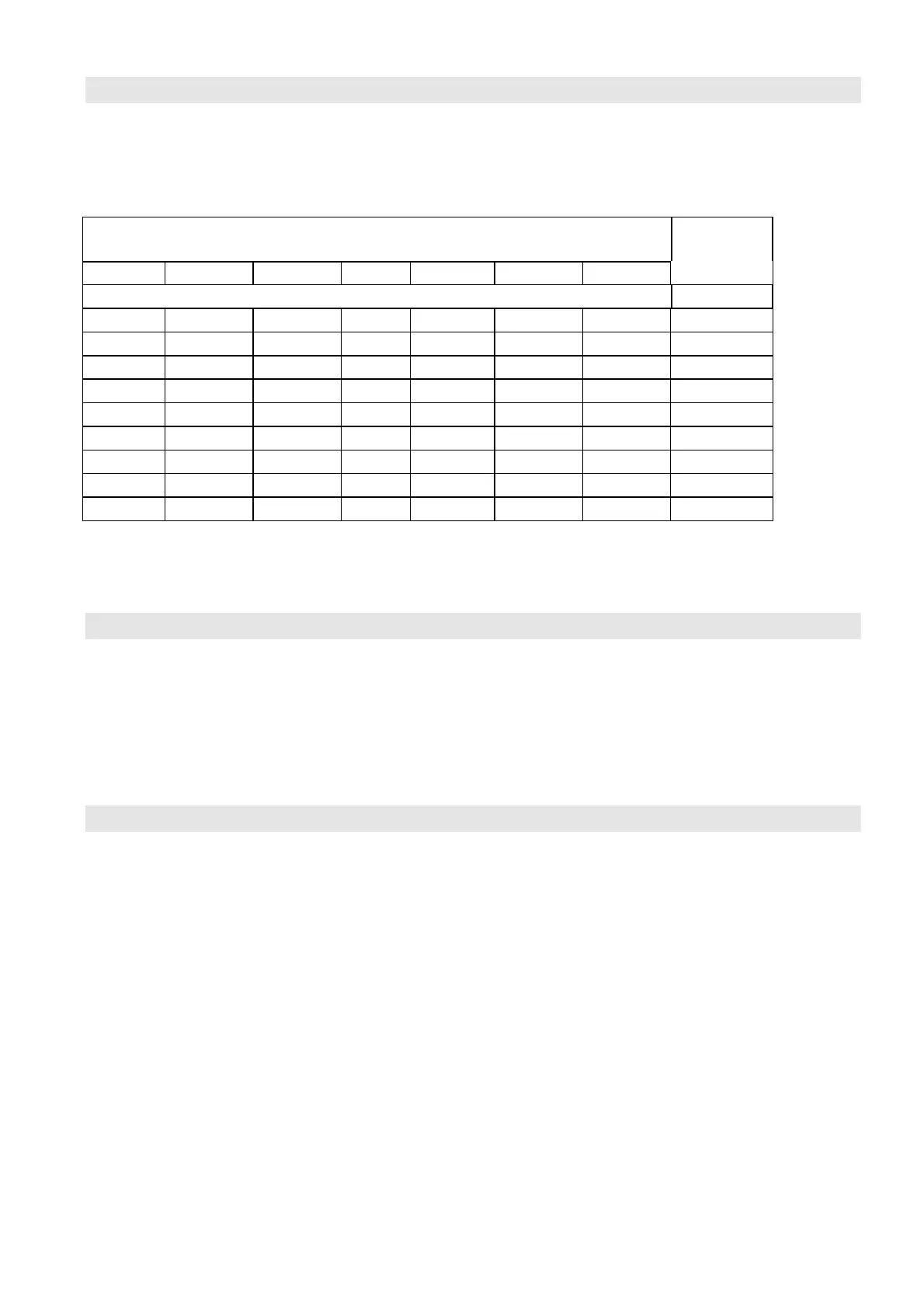
Maximum permissible value of harmonic in % of the fundamental
frequency current
3rd 5th 7th 11th 13th 17th 19th Display
not activated
OFF
10 10 7 5 4 3 3
1
15 15 12 8 6 5 4
2
20 20 14 9 8 6 5
3
25 25 18 11 10 7 7
4
30 30 21 14 12 9 8
5
35 35 25 16 13 10 9
6
40 40 29 18 15 12 11
7
45 45 32 20 17 13 12
8
50 50 36 23 19 15 13
9
If RST is selected (see page 20), OFF is reset.
6.3.18. Parameter -18- : C.T. transformation ratio k
The current transformer transformation ratio k can be set by means of parameter 18. The displayed
current values and C/k values will be respectively multiplied by the set factor. Factors between 1 and
8000 can be selected. This is possible in all the initialization modes.
If RST is selected (see page 20), 1 is reset.
6.3.19. Parameter -19- : Time delay for switching out steps in case of ≡I and ≡E
If fault alarm is given as a consequence of undercurrent ≡I and energy feed-back ≡E , capacitor steps
can be switched out after the set waiting delay has elapsed. The switch-out function has to be released
via parameter 14. Waiting delays between 30 and 500 seconds can be set.
Step width is 10 seconds (range of 30 – 200), 20 seconds (range of 200 – 300) and 50 seconds (range
of 300 – 500).
If RST is selected (see page 20), 500 is reset.


 To Next Page