Issue February 2002
Document Number: 13124
- 7 -
percentage values up to the 17th harmonic. If harmonic generators exist and if the resonance frequency
between the compensation equipment and the line transformer is on a typical harmonic frequency, the
percentage part of this harmonic increases excessively. This may activate alarms by means of various
limit-value profiles. This may be, for example, an audible or an optical signal via the alarm relay.
The root-mean-square current is determined by calculation on the basis of the current's curve shape.
Non-linear consumers distort the sinusoidal shape of the current. Fundamental frequency current and
root-mean-square current are of different values in case of harmonic load. The higher the portion of
harmonic load the higher is the deviation between the values of the fundamental frequency current and
of the root-mean-square current. A factor which is created from these two values is a parameter
portraying the harmonic status, and can be determined by means of settable limit values to be used for
the alarm.
2.10. Measurement of temperature
Via an internal temperature sensor the ESTAmat PFC Controller can permanently measure the
ambient temperature. Although the sensor is installed within the device, the measuring can be carried
out with sufficient precision because of the existing venting slots which allow sufficient air circulation.
When the Controller is mounted into a switch cabinet, there is the possibility of monitoring the
cabinet's internal termperature. By setting limit values, an alarm function can be activated.
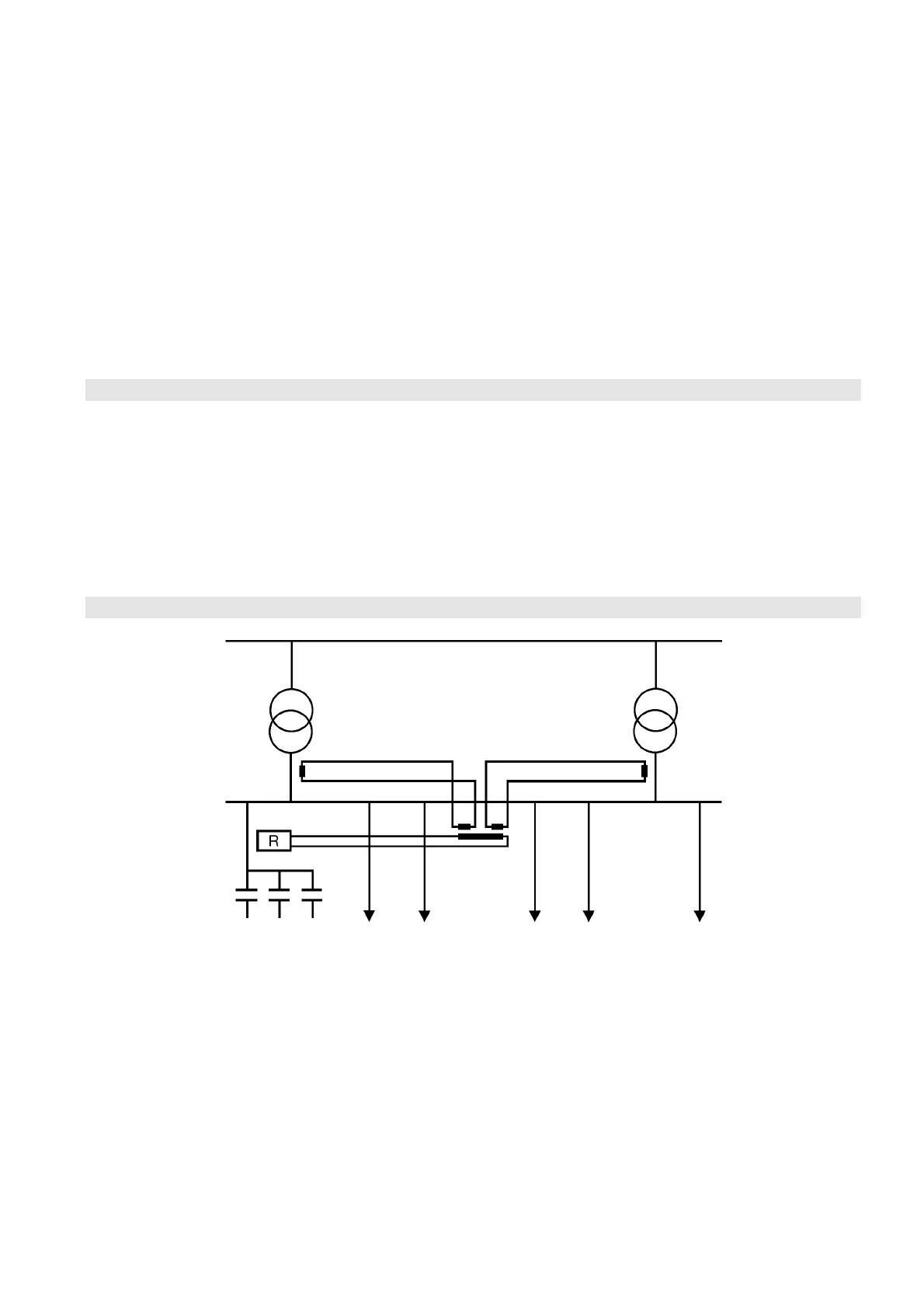
2.11. Summation current transformer
When several transformers supply one single L.V. bus bar, the individual currents shall be measured
by means of current transformers and then added together via a summation current transformer.
Special attention shall be given to the correct polarity because, otherwise, the current intensities of the
individual transformers will subtract.
The calculation of the C/k-value is described under item 6.3.5. It is important to remember that the
transformation ratios of the individual current transformers shall be added up.
k = k1 + k2 + k3 ... k = ∑ C.T. transformation ratios