Advent Communications
209297 – DCU5000 Drive Control Unit Page 10 of 42
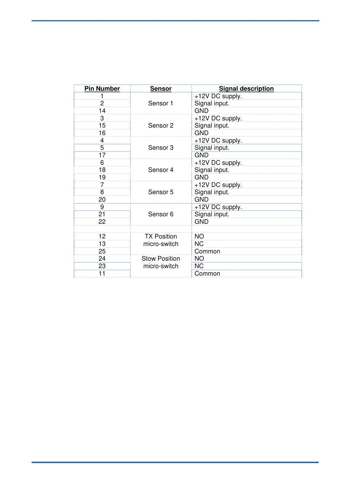
3.3. SENSORS 1
This interface is designed to interface with any position, limit switches or sensors fitted
to the antenna.
Detailed descriptions are beyond the scope of this manual. Contact Advent
Communications for further guidance and information.
Connector: 25-pin male D-type.
Pin Number
Sensor Signal description
1
Sensor 1
+12V DC supply.
2 Signal input.
14 GND
3
Sensor 2
+12V DC supply.
15 Signal input.
16 GND
4
Sensor 3
+12V DC supply.
5 Signal input.
17 GND
6
Sensor 4
+12V DC supply.
18 Signal input.
19 GND
7
Sensor 5
+12V DC supply.
8 Signal input.
20 GND
9
Sensor 6
+12V DC supply.
21 Signal input.
22 GND
12 TX Position
micro-switch
NO
13 NC
25 Common
24 Stow Position
micro-switch
NO
23 NC
11 Common