Advent Communications
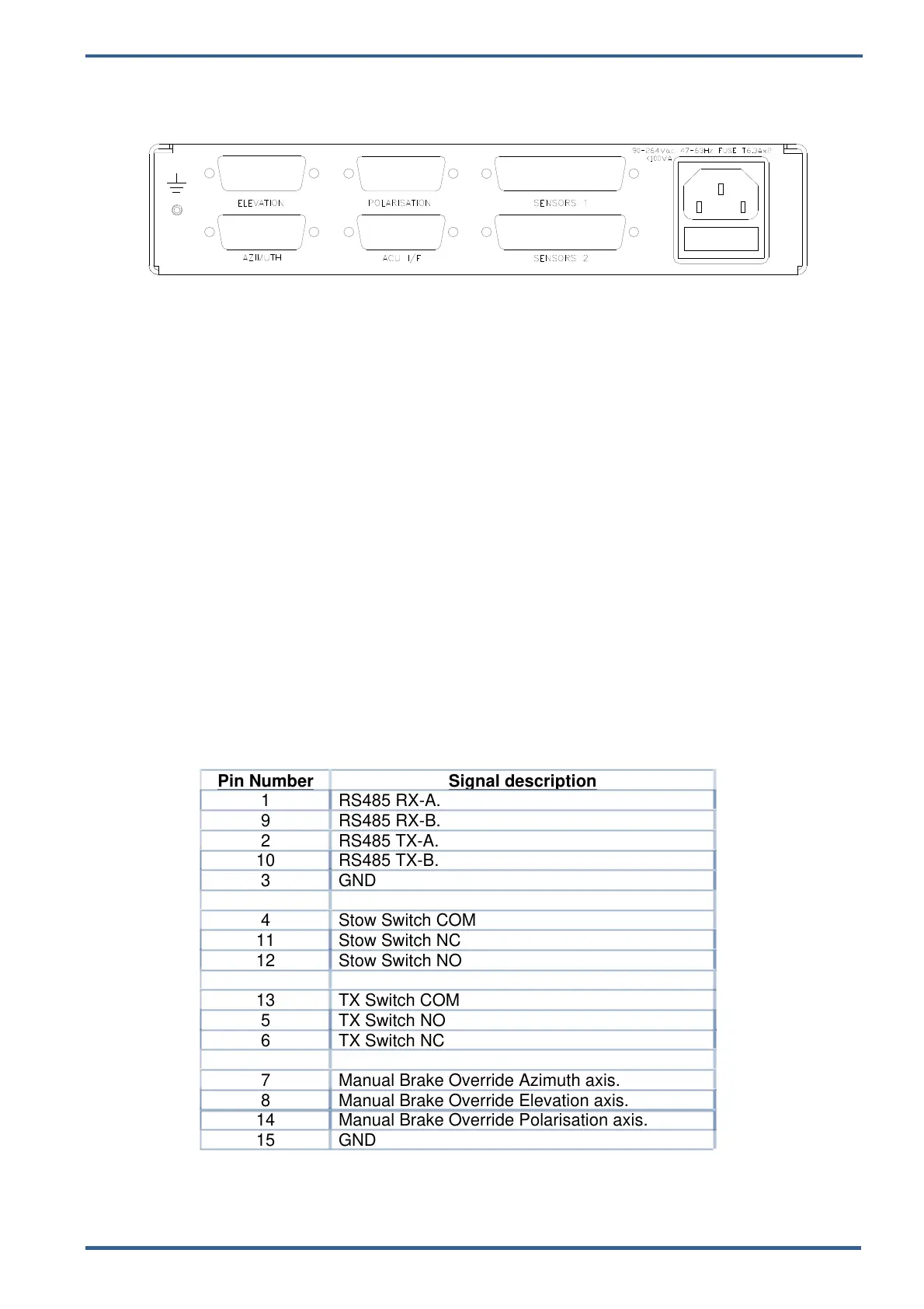
3. REAR PANEL
!CAUTION: The side ventilation grills must be kept clear to allow adequate airflow
3.1. AC POWER
Power in the range 90 – 264Vac is connected by means of a 3 pin IEC connector at
the rear panel.
Live & Neutral conductor fusing is employed.
The two fuses integrated into the IEC connector should be ceramic at T6.3A rating
each.
The total power consumption is typically less than 100watts.
!NOTE: A separate EMC earth should be connected to the earth point provided.
3.2. ACU I/F
This is designed to directly connect to the serial communications cable from an Advent
SatFinder, ACU4XXX or ACU5XXX control unit.
Detailed descriptions are beyond the scope of this manual. Contact Advent
Communications for further guidance and information.
Connector: 15-pin female D-type.
Pin Number
Signal description
1 RS485 RX-A.
9 RS485 RX-B.
2 RS485 TX-A.
10 RS485 TX-B.
3 GND
4 Stow Switch COM
11 Stow Switch NC
12 Stow Switch NO
13 TX Switch COM
5 TX Switch NO
6 TX Switch NC
7 Manual Brake Override Azimuth axis.
8 Manual Brake Override Elevation axis.
14 Manual Brake Override Polarisation axis.
15 GND
209297 – DCU5000 Drive Control Unit Page 9 of 42