Advent Communications
209297 – DCU5000 Drive Control Unit Page 11 of 42
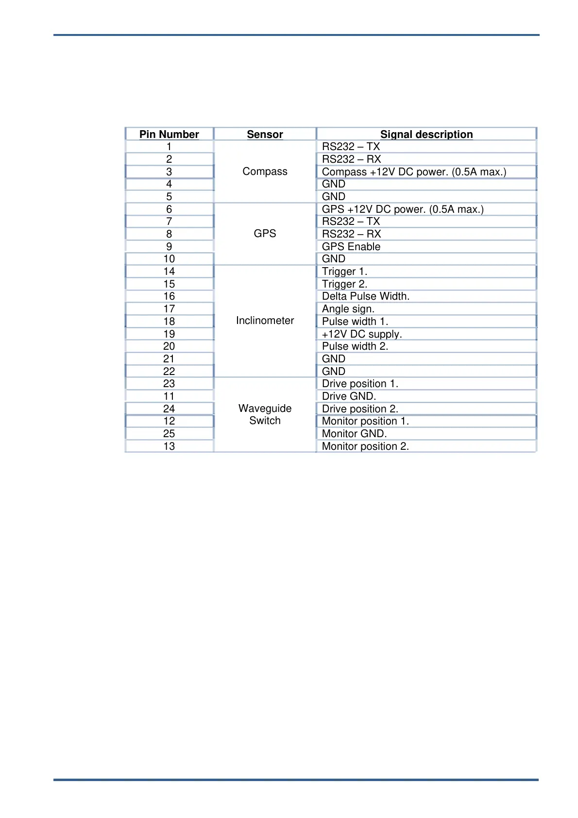
3.4. SENSORS 2
This interface is designed to interface with any antenna fitted compass, GPS,
inclinometer or waveguide switch.
Detailed descriptions are beyond the scope of this manual. Contact Advent
Communications for further guidance and information.
Connector: 25-pin female D-type.
Pin Number
Sensor Signal description
1
Compass
RS232 – TX
2 RS232 – RX
3 Compass +12V DC power. (0.5A max.)
4 GND
5 GND
6
GPS
GPS +12V DC power. (0.5A max.)
7 RS232 – TX
8 RS232 – RX
9 GPS Enable
10 GND
14
Inclinometer
Trigger 1.
15 Trigger 2.
16 Delta Pulse Width.
17 Angle sign.
18 Pulse width 1.
19 +12V DC supply.
20 Pulse width 2.
21 GND
22 GND
23
Waveguide
Switch
Drive position 1.
11 Drive GND.
24 Drive position 2.
12 Monitor position 1.
25 Monitor GND.
13 Monitor position 2.