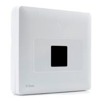
1.1 System Features
The following table lists the PowerMaster-33 features with a description of each feature and how to use it.
Feature Description How to configure and use
Visual Alarm
Verification
The PowerMaster-33 when used with the
Next CAM PG2 PIR-camera detector and
cellular or IP communication is able to
provide the Monitoring Station with clips
captured in alarm situations. The system
sends the clips to the Monitoring Station
automatically for burglary alarms and
depending on setup, also for fire and
personal emergency alarms.
1. Setup cellular communication: see
Cellular Module Installation section 3.5)
2. Configure camera settings: refer to the
Next CAM PG2 Installation Instructions
3. Enable fire and personal alarm
verification: see KP-250 PG2 Installer’s
Guide, section 3.6.6 Configuring Motion
Cameras for Video Alarm Verification
On demand clips from
cameras
The PowerMaster-33 can provide images
from the Next CAM PG2 by demand from a
remote PowerManage server. Pictures are
taken based on a command from the
monitoring station. To protect customers'
privacy, the system can be customized to
enable the "On Demand View" only during
specific system modes (Disarm, Home,
Away) and also to a specific time window
following an alarm event.
1. Setup the On demand feature: see
KP-250 PG2 Installer’s Guide, section 3.6.6
Configuring Motion Cameras for Video Alarm
Verification
2. To request and view images: refer to the
PowerManage User's Guide, Chapter 5
Viewing and Handling Events
Easy Enrollment PowerG devices are enrolled from the control
panel. Pre-enrollment can also be performed
by entering the PowerG device ID number
and then activating the device in the vicinity
of the panel.
To enroll or pre-enroll devices: see
KP-250 PG2 Installer’s Guide, section 3.4.2
Adding New Wireless Devices or Wired
Sensors
Device Configuration Device parameters and related system
behavior can be configured from the KP-250
PG2 keypad or from a remote location.
Each PowerG device has its own settings. To
configure these settings through the KP-250
PG2 keypad, enter the DEVICE SETTINGS
menu.
PG2: see KP-250 PG2 Installer’s Guide,
Chapter 3 Programming and also the
individual device's Installation Instructions.
To configure devices from a remote
location: refer to the PowerManage User's
Guide Chapter 3 Working with Panels and to
the Remote Programmer PC software User's
Guide, Chapters 6 and 7.
Diagnostics of the
control panel and
peripherals
You can test the function of all wireless
sensors deployed throughout the protected
area to collect information about the received
signal strength from each transmitter, and to
review accumulated data after the test.
To perform diagnostics and to obtain
signal strength indication: see KP-250
PG2 Installer’s Guide, section 3.9
Diagnostics
Conducting periodic
tests
The system should be tested at least once a
week, and after an alarm. The periodic test
can be conducted locally or from a remote
location (with the assistance of a non-
technical person at the location).
To conduct a walk test locally: see KP-250
PG2 Installer’s Guide, Chapter 4 Periodic
Test by Installer Code or KP-250 PG2 User’s
Guide, Chapter 8 Periodic Test by User
Code
To conduct a walk test from remote
location: refer to the Remote Programmer
PC software User's Guide, Chapter 6 Data
Details Tables.
D-306917
PowerMaster-33 G2 Installer's Guide 3

 Loading...