DE5465 7
C. MCT-134 / 104* (Fig. 13):
(N.A. in North America)
4-button hand-held units. MCT-
134 (CodeSecure) can replace
the MCT-234 keyfob. MCT-104
(PowerCode) can perform
emergency and non- alarm
functions. Both units look alike.
Figure 13. MCT-134 / 104
D. MCT-132 / 102* (Fig. 14):
(N.A. in North America) 2-
button units. MCT-132
(CodeSecure) can perform
functions as shown.
MCT-
102 (PowerCode) can
perform emergency and non-
alarm tasks. Both units look
alike.
Figure 14. MCT-132 / 102
E. MCT-131 / 101* (Fig. 15):
(N.A. in North America) Single-
button units. The MCT-131
(CodeSecure) and the MCT-
101 (PowerCode) can be
enrolled to perform functions as
shown. Both units look alike.
Figure 15. MCT-131 / 101
F. MCT-211* (Fig. 16) Water-
proof,
wrist-worn PowerCode
transmitter. Can be enrolled
to perform emergency or
non-alarm functions.
Figure 16. MCT-211
* Not UL-listed - not to be used in UL-listed systems
3.9 PowerMax+ Compatible WL Siren
The MCS-700 (*) wireless siren (fig. 17) can be
integrated with the PowerMax+ in areas in
which wiring action is difficult or impossible.
The MCS-700 is a fully supervised, 2-way
communication device (it includes a receiver,
to receive activation commands from the alarm
system, and a transmitter to periodically
transmit its status signal to the alarm system).
Figure 17
Wireless
Siren
When an identifiable activation command is received from
the PowerMax+, the siren activates its sounder and the flash
light (strobe light every 1.5 seconds).
* Not UL-listed - not to be used in UL-listed systems
3.10 Installing an Optional X-10 Siren
(Not to be used in UL-listed systems)
If you need a “wireless” external siren, you may install an X-
10 siren module which is triggered by a signal transmitted
via the built-in electrical wiring of the protected site. This
siren can replace the regular external siren or complement it
without laying out additional wires. Of course, such a siren
can be used only in conjunction with an optional power-line
interface module.
The X-10 siren is ready to function upon connection to an
electrical power outlet, without re-programming the Power-
Max+. You only have to set the HOUSE CODE and the
UNIT CODE selectors on the X-10 siren as follows:
House Code: Set this selector to the letter that follows, by
alphabetical order, the letter that you programmed as a
house code for the protected premises. For example, if the
programmed house code is “J”, set the siren house code
selector to “K”.
Note: If the programmed house code letter is “P” (which is
the last programmable letter), select “A” for the siren.
Unit Code: The siren will function only if you set the unit
code selector to “1”.
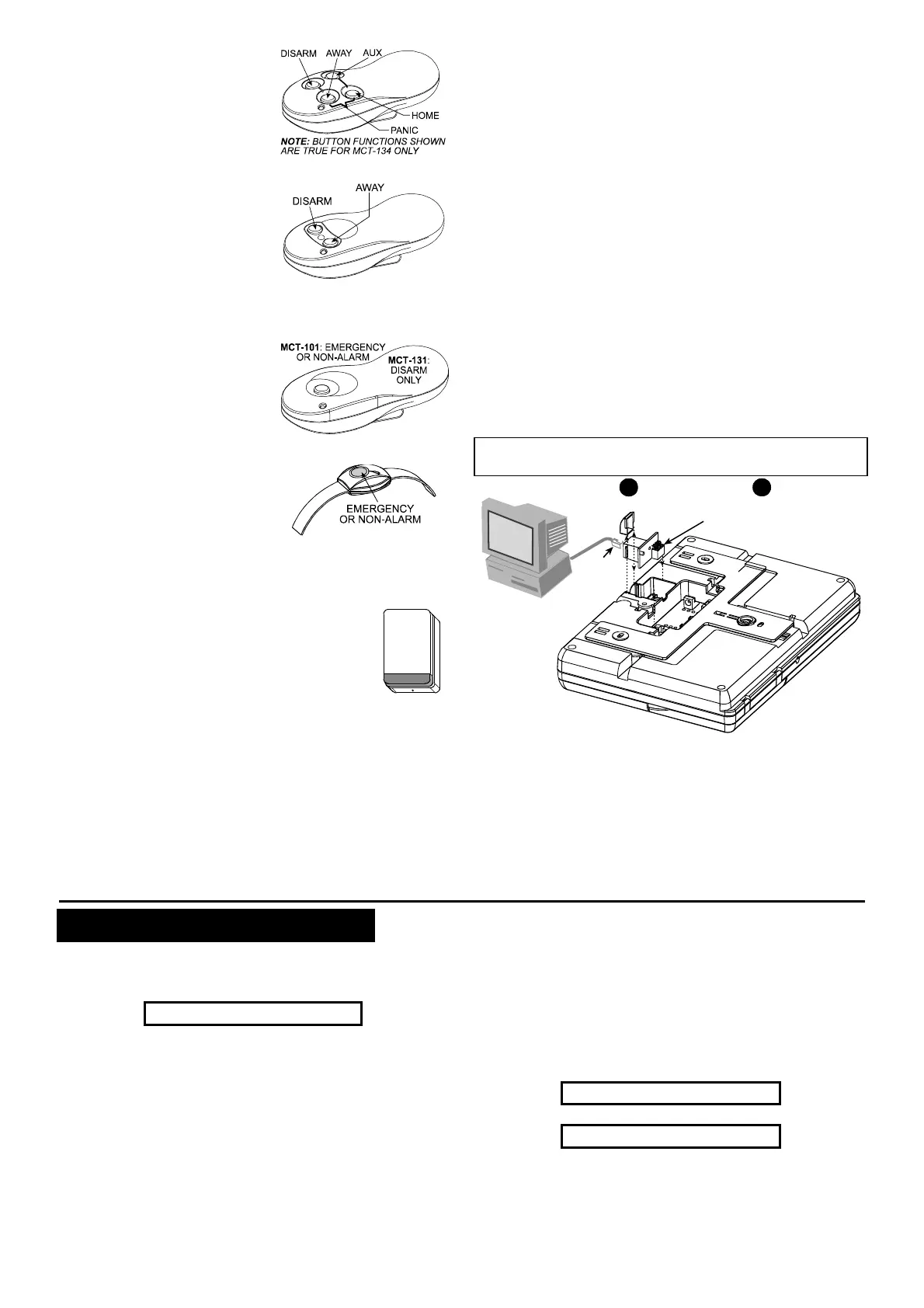
3.11 Connecting PowerMax+ to a Computer
The control panel can be equipped with an optional RS232
module for serial data interchange with a local computer. If
this module is not supplied, a special plastic cap blocks the
niche designed to accommodate the module.
Attention: For data download from a local computer, the
PowerMax+ must be set to the installer mode.
Insert the RS-232 adapter
into its male connector,
until a click is heard
21
Remove plastic cap
RJ-45
or
RJ-31X
(USA)
Figure 18 - Connecting the PowerMax+ to a Computer
3. 12 Connecting PowerMax+ to GSM Modem
The GSM unit enables the PowerMax+ system to operate
over cellular network. For details regarding the GSM
modem features and connections, refer to the GSM
Modem installation instructions.
4. TESTING PROCEDURES
4.1 Preparations
Make sure all windows and doors are closed. If all zones
are secured (undisturbed), the display should read:
READY HH:MM
If the display is “NOT READY”, query the control panel by
pressing the <SHOW/OK> button repeatedly. The
source(s) of the problem(s) will be displayed and read
aloud. Take the necessary measures to eliminate the
problem(s) before testing the system (see 4.2 below).
4.2 Diagnostic Test
To verify proper function of all detectors in the system, a
comprehensive diagnostic test is required. To perform this
test, refer to figure 9 in the Programming Guide.
4.3 Keyfob Transmitter Test
Initiate transmission from each transmitter enrolled as a
keyfob unit (according to the list in Table A2, Appendix A).
Use each transmitter to arm the control panel AWAY and
immediately disarm it. Upon pressing the keyfob unit’s
AWAY key, the ARM indicator should light.
The display should respond as follows:
ARMING AWAY
Ð
PLEASE EXIT NOW
The exit delay beeps will begin.