8 DE5465
Press the keyfob unit’s DISARM ( ) key. The ARM indicator
should extinguish, the announcement “Disarm, ready to arm"
should be heard and the display should revert to:
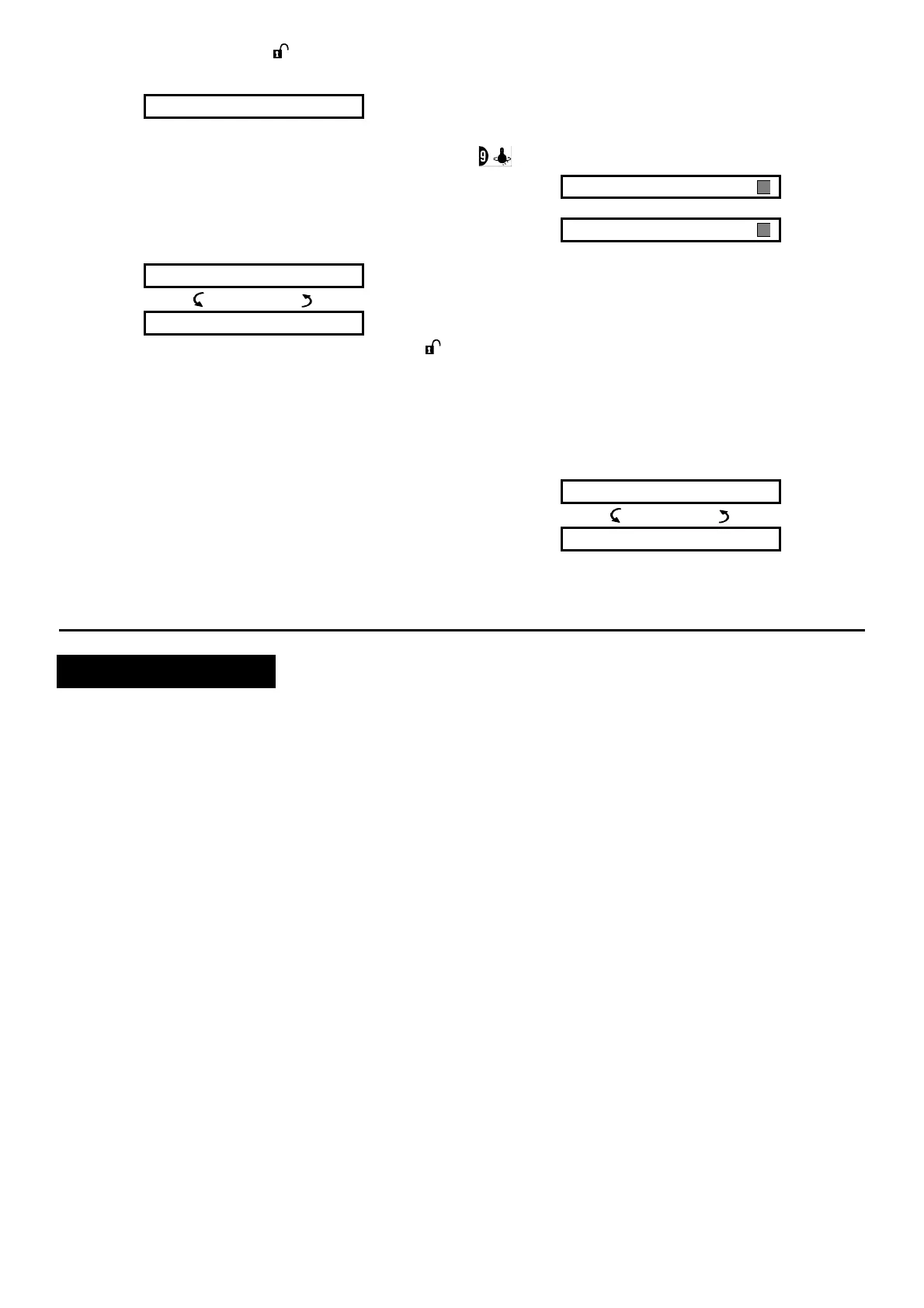
READY HH:MM
Test the AUX button in each keyfob in accordance with the
information noted in Table A.2, Appendix A. Verify that the
AUX button performs its duty as programmed.
If the AUX (
@) button is defined as “STATUS”, system
status should be displayed and announced upon
pressing the button.
If the AUX (
@) button is defined as “INSTANT”, press
the AWAY button and then the AUX button. The
response should be:
ARMING INSTANT
(alternating)
PLEASE EXIT NOW
and the exit delay beeps will start. Press the DISARM ( )
key immediately to disarm.
If the AUX (
@) button is programmed as “PGM / X-10”
and permitted to activate one or several X-10 units,
pressing (
@) should activate the appliance controlled by
the chosen X-10 unit(s).
If the AUX (
@) button is programmed as “PGM / X-10”
and permitted to activate the PGM output, pressing (
@)
should activate the device wired to the PGM output.
4.4 Appliance ON/OFF Test
The “X-10 unit assignment” information that you noted in
Appendix B of this manual is very useful for this test.
Go over the table in Appendix B column by column. If, for
instance, the “BY ARM AWAY” column has “X”s marked in
the rows pertaining to units 1, 5 and 15 - then arm AWAY
the system and verify that the appliances controlled by
these units are actually activated upon arming.
Continue in the same manner in the following columns,
always creating the state or event that will activate the
relevant units. Verify that all appliances are activated as
programmed.
IMPORTANT! Before testing “BY TIMER” and “BY ZONE”,
make sure that these forms of control are permitted - click
repeatedly and verify that the display shows:
BY TIMER ON
and:
BY SENSOR ON
A dark box at the extreme right means that these functions
are enabled.
The easiest way for test timed activation is to select the
ninth item in the installer’s menu (”10. USER SETTINGS”)
and set the system clock a few minutes before the relevant
“start time”. Do not forget to return the clock to the correct
time after completion of this test.
4.5 Emergency Transmitter Test
Initiate transmission from each transmitter enrolled to an
emergency zone (according to the list in Table A3,
Appendix A). For example, upon pressing the transmit
button of an emergency transmitter enrolled to zone 22,
the display should read:
Z22 EMERGENCY
(alternating)
VIOLATED
It is advisable to let the central station know that you are
conducting this test, or just disconnect the telephone line
from the PowerMax+ during the test, to prevent false alarms.
5. MAINTENANCE
5.1 Dismounting the Control Panel
A. Release the PowerMax+ unit from its bracket, as shown
in figure 2, step 1-5.
B. Separate the PowerMax+ unit from its bracket.
5.2 Replacing the Backup Battery
Replacement and first-time insertion of battery pack is
similar (see figure 1).
With fresh battery pack, correct insertion and tightened
battery compartment lid, the TROUBLE indicator should
extinguish. However, the “MEMORY” message will now
blink in the display (caused by the “tamper” alarm you
triggered when opening the battery compartment lid).
Clear it by arming the system and immediately disarming.
5.3 Fuse Replacement
The PowerMax+ has two internal fuses that have
automatic reset. Therefore, there is no need to replace
fuses.
When overcurrent condition occurs, the fuse cuts off the
circuit current. Upon fault current being removed, the fuse
is automatically resetted and allows current flow through
the circuit again.
5.4 Replacing/Relocating Detectors
Whenever the maintenance work involves replacement or
re-location of detectors, you must keep in mind the
requirement to provide a 6 dB safety margin for signal
reception. It is therefore mandatory to perform a full
diagnostic test according to Section 9 of the
Programming Guide.
Remember! A "poor" signal is not acceptable, as stated at
the end of the test procedure.