EasyManua.ls Logo

VitalConnect Platform - Page 16

VitalConnect Platform
20 pages
Print Icon
To Next Page IconTo Next Page
To Previous Page IconTo Previous Page
Loading...
IFU-01, Rev. A Page 16 of 20
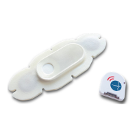
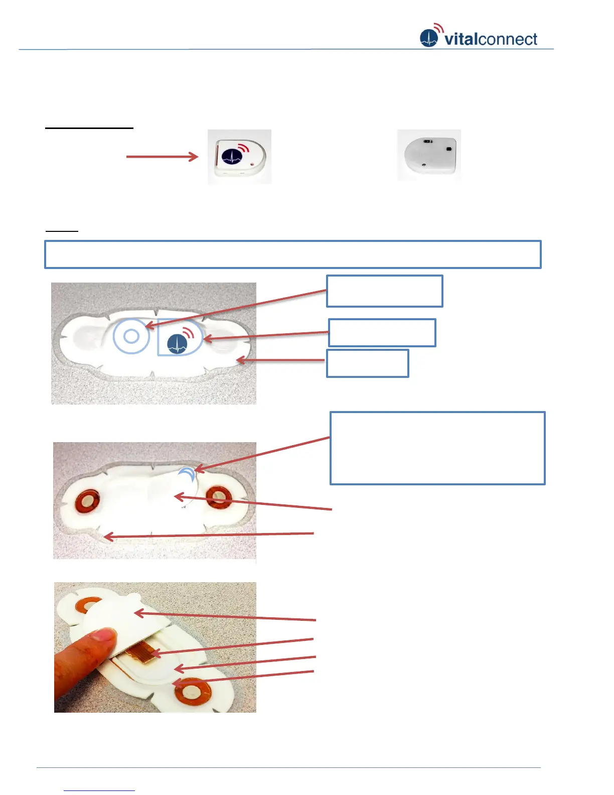
VitalConnect Sensor - Assembly Instruction (bottom entry):
Sensor Module
Patch
Module
Connector
Figure 1: Front logo side
Figure 2: Back side
Connector Tongue (2)
Module compartment/ cavity (3)
Figure 5: Inside patch
Paper Liner of Back Flap (5)
2
5
1
3
Figure 4: Adhesive Side
Back Flap (1)
Clear Release Liner (6)
1
6
* Crescent shaped tab located at the
edge is designed to help you grip and
move the flap.
Figure 3: Front of patch
* Battery side
* Module side
* Blue outline shown on Figure-3 below is for visualization and may not be indicated on the patch
Wing side
4
Module cavity adhesive rim (4)

Related product manuals