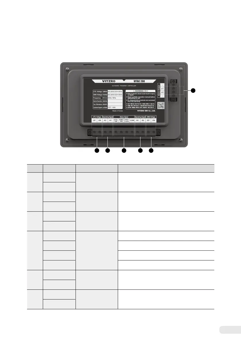
3. 2 Composition of the rear unit
No. Terminal name Name Description
①
a1
Alarm Output
Fault alarm contact output terminal
(Outputs when switchover fails or the controller is
abnormal.)
a2
②
UP
Utility Voltage
Commercial power input terminal
UN
③
A1
Operating Signal
Switch on contact output terminal at the use power side
A2
④
UTIL ON
Status Signal
Switch status input terminal at the commercial power side
EMG ON
Status input terminal at the emergency power side
Inter-Lock
Interlock status input terminal
COM
Input common terminal
⑤
B1
Operating Signal
Switch on contact output terminal at the emergency
power side
B2
⑥
EP
Emergency Voltage
Emergency power input terminal
EN
(Detailed description of the rear unit)
2 53 64
1