VIVOTEK
User's Manual - 27
1. The DO+ pin provides a 5V output, and the max. load is 50mA.
2. The max. voltage for DO- pins is 30VDC (External power).
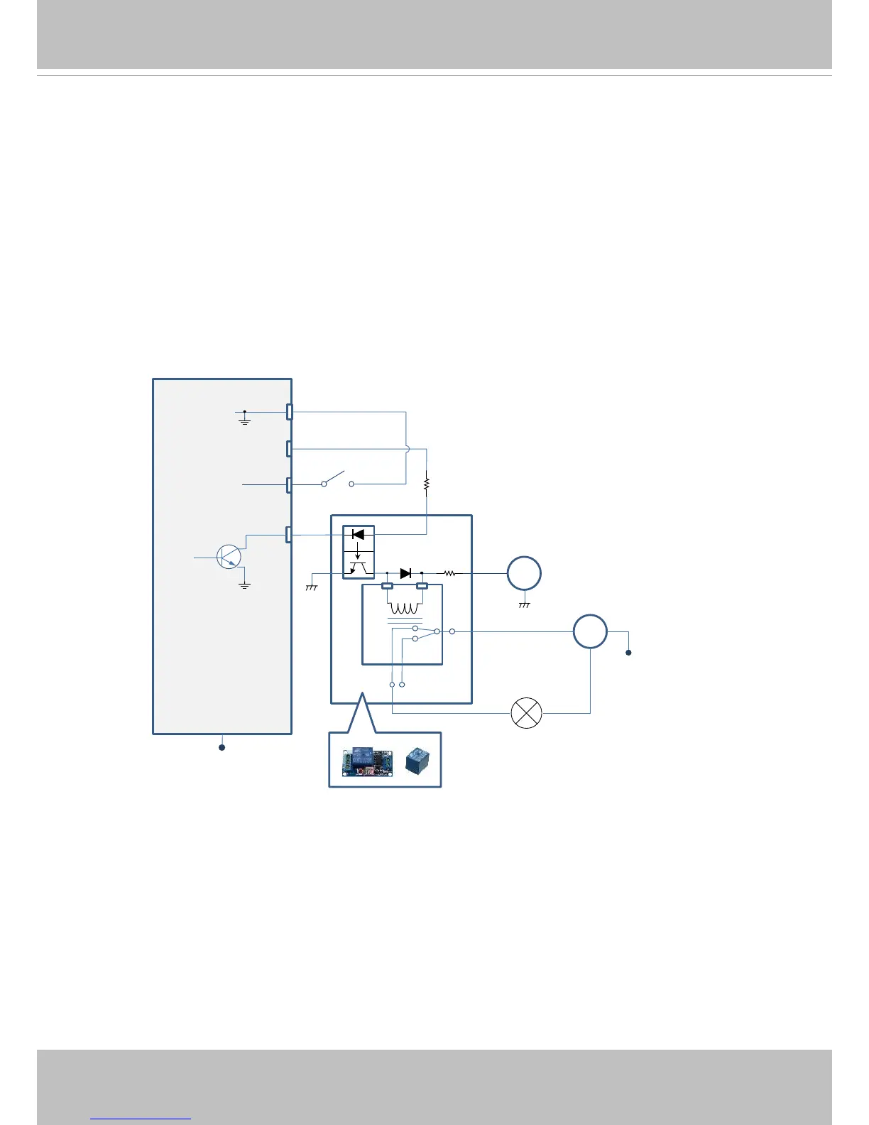
In order to control AC devices, the following diagram can be taken into consideration.
This diagram uses a relay to control the ON/OFF condition of the AC device.
3. An external relay can be triggered by using the DO+ or by an external power source,
depending on the type of relay you use.
4. In case of using an individual relay (instead of using a relay module), for protection
against voltage or current spikes, a transient voltage suppression diode must be
connected in parallel with the inductive load.
DI-
DO+
DI+
DO-
Switch
External Device
External DC power
Dry contact with external DC power source to supply a relay. Dry contact is the safest connecon
to protect devices.
NC
NO
Relay
Photo
Coupler
DC
DC 0V
DC 0V
External AC power
with Protected Earth
AC
PE
PE
DI/DO Diagram
 Loading...