VIVOTEK
30 - User's Manual
Network Deployment
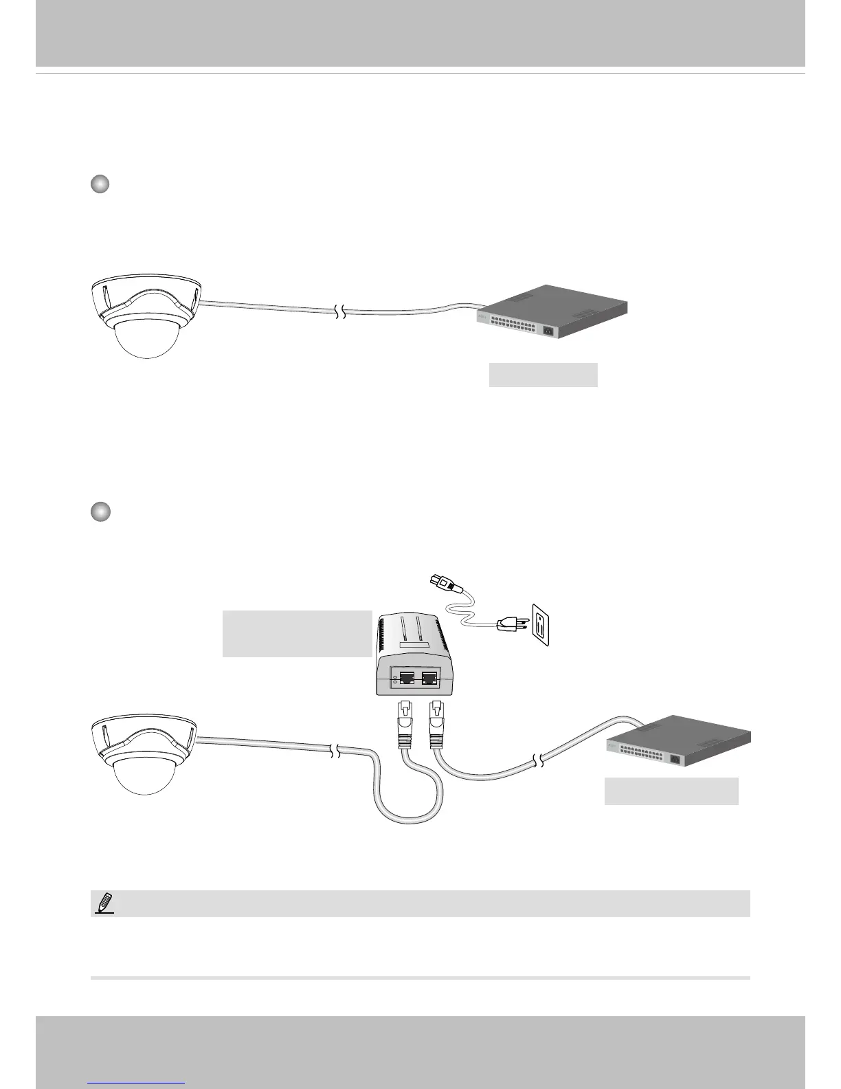
General Connection (PoE)
When using a PoE-enabled switch
The Network Camera is PoE-compliant, allowing transmission of power and data via a sin-
gle Ethernet cable. Follow the below illustration to connect the Network Camera to a PoE-
enabled switch via Ethernet cable.
PoE Switch
When using a non-PoE switch
Use a PoE power injector (optional) to connect between the Network Camera and a non-
PoE switch.
Non-PoE Switch
PoE Power Injector
(optional)
NOTE:
1. The camera is only to be connected to PoE networks without routing to outside plants.
2. For PoE connection, use only UL listed I.T.E. with PoE output.
802.3af
802.3at for FD9367-EHTV
802.3at for FD9367-EHTV