EN - 4
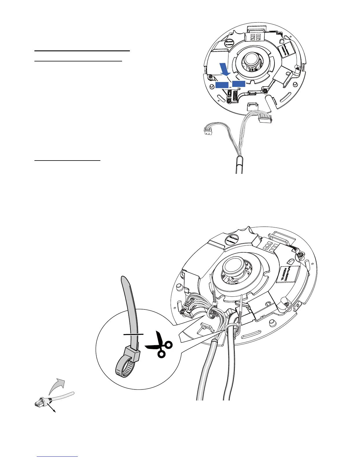
Connect the supplied power & IO cables if your
switch does not support PoE. Connect the white
header connectors to J12 and J7 on the camera.
Power and IO
cables
Connecting Ethernet Cable
& the Power and IO Cable
Connecting Cables
If you need to route cables through the side opening, proceed with the following:
1. Connect the Ethernet and the Power & IO cables. The Ethernet cable is user-supplied.
2. Use the included cable ties to secure the Ethernet and IO cable to the base plate. Insert the cable
ties through the vertical mounting tabs on the side of the plastic cover and on the edge of the
cabling cutout.
3. Arrange the cables neatly to avoid getting in the way when the dome cover is attached.
4. Cut the extra length from the cable tie.
It is recommended to remove the strain relief boot if your Ethernet cable
comes with one.
J12
J7
Ethernet
Power & IO Cable
Strain relief boot
If you route cables through a drill hole on
a wall/ceiling, simply route cables through
the cabling cutout.
 Loading...