EN - 7
English
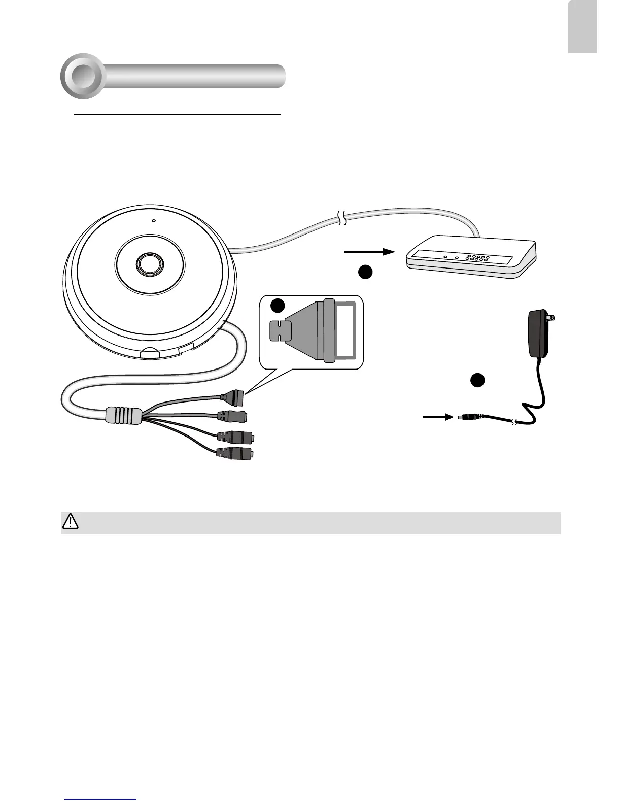
1. Connect RJ45 Ethernet cable to a switch.
2. Connect the power cable from the Network Camera to a power outlet.
3. If you have external devices such as sensors and alarms, make the connection from the general
I/O terminal block.
General Connection (without PoE)
Network Deployment
4
POW
ER
C
O
LL
I
S
ION
L
I
N
K
RECEIVE
PARTITIO
N
1
2
3
4
5
+5V
DO
D1
GND
1
2
3
General I/O Terminal Block
Power Cord Socket (Black)
Microphone In (Pink)
Audio Out (Green)
+5V: Power, 5V DC
DO: Digital Output
D I: Digital Input
GND: Ground
IMPORTANT:
1. When IR lights are on in the night, the total power consumption is 23W.
2. If DC power is preferred, it should comply with: O/P: 12VDC, 2A min., L.P.S. per IEC 60950-1.
 Loading...