EN-5
English
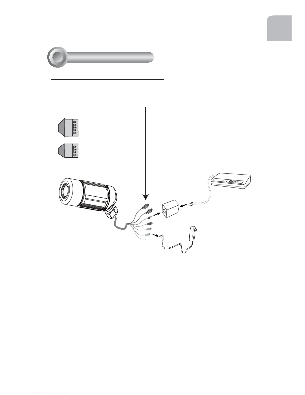
Network Deployment
4
PO
W
ER
C
O
L
L
I
S
I
ON
L
I
N
K
R
E
CEI
V
E
P
ARTI
TI
ON
1
2
3
4
5
1. If you have external devices such as
sensors and alarms, make connections
from general I/O terminal block.
2. Use the supplied RJ45 female/female
coupler to connect the Network Camera
to a switch.
Use Catagory 5 Cross Cable when
Network Camera is directly connected
to PC.
3. Connect the power cable from the
Network Camera to a power outlet.
N.C.
485B
485A
AC24V
AC24V
N.C.: No Connector
485B: RS485-
485A: RS485+
AC24V: Power in AC 24V
AC24V: Power in AC 24V
G N D : Ground
D I : Digital Input
D O : Digital Output
+12V : Power, 12V DC
GND
DI
DO
+12V
General Connection (without PoE)