VIVOTEK
User's Manual - 9
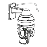
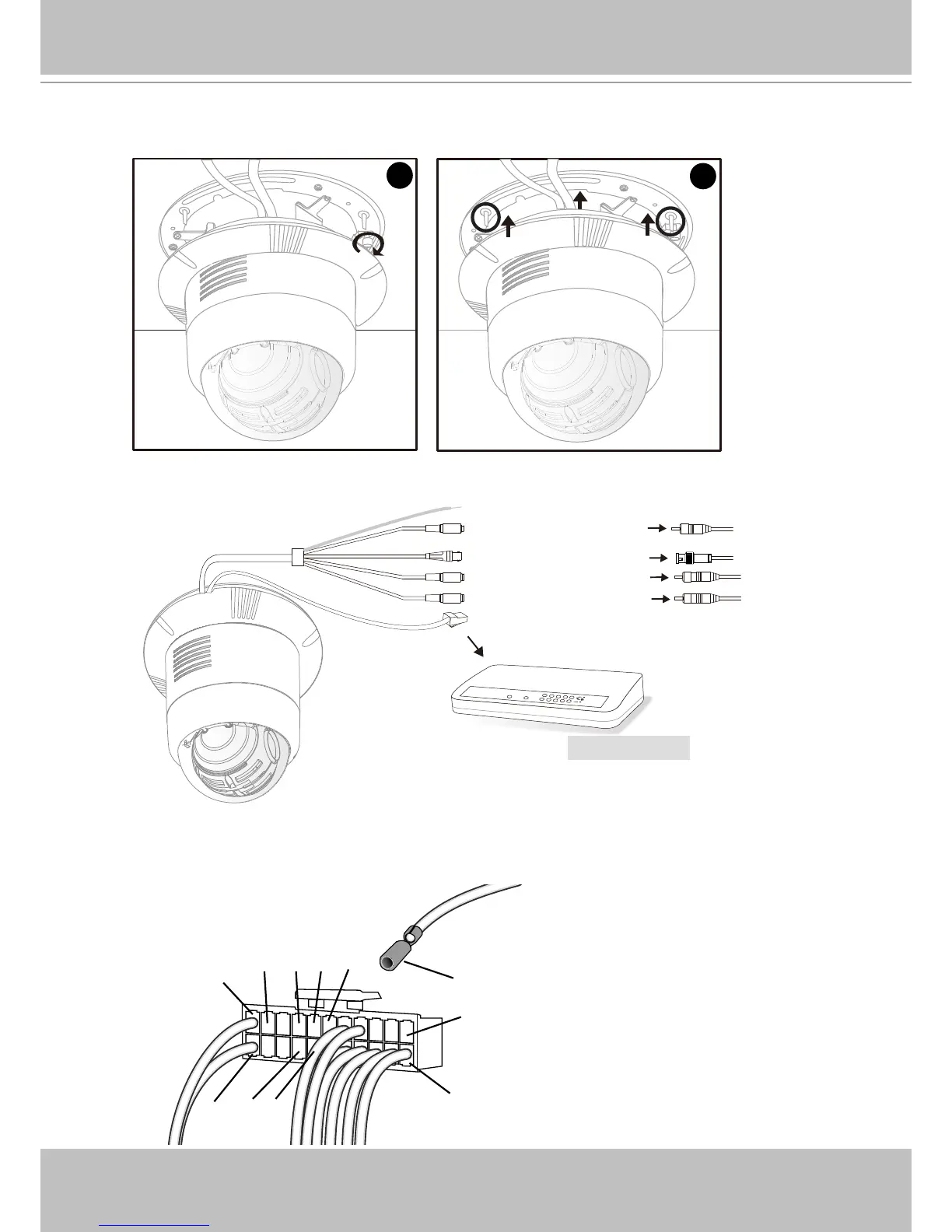
10. Tighten the screw on the xing plate.
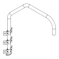
11. Align the three holes to mount the decoration ring.
12. Connect the cables and make the network deployment.
13. If you have external sensors or alarms, insert lines from the DI/DO cable (those with terminal
crimps) to pins #12 ~ #16 on the combo cable connector.
11
10
POWER
COLLISION
LINK
RECEIVE
PARTITION
1
2
3
4
5
Ethernet Switch
Power Cord Socket
BNC Video Out
Microphone In (pink)
Audio Out (green)
Ethernet 10/100 RJ45 Plug
Ground
21
22
1
2
12
13
15
1416
DI 0
DI 2DI 3
DI 1DO
When combo cable is connected
to camera
Terminal Crimp
Lines from
the I/O cable
Combo Cable
Connector
20
GND