31
8.1 EXTERNAL WIRING
basic operation of the boiler via the mode selector switch. If
external controls are to be added to the system, they must be
connected to the appliance as shown in the following diagrams.
For advice on controls that are not featured in this book, please
contact Vokèra technical on 0844 391 0999.
8.1.1 EXTERNAL WIRING LIMITATIONS
Low voltage and High voltage cables must be run separately.
Any external wiring must remain within the limits as detailed:
room thermostat = 30-metres
8.1.2 OUTSIDE SENSOR
The outside sensor can be connected via a controls interface
which enables a connection to be made directly on the PCB
at plug CN6 (see Fig)
8.2 OTHER DEVICES
Contact the controls manufacturer and/or Vokèra technical
suitability of a particular control. Further guidance on the recom-
mended practice for the installation of external controls, can be
IMPORTANT
• The boiler must always be supplied with a permanent 230V
electrical supply.
• The room thermostat connection is low voltage (24 Vdc)
• Do not connect any controls or auxiliary equipment to the
low-voltage terminal strip, other than that approved/supplied
by Vokèra Ltd.
Fig. 45
SECTION 8 - WIRING DIAGRAMS
Room Thermostat (24 Vdc)
20
30
40
50
60
70
80
90
100
-20
0,2
0,4
0,6
0,8
1,0
1,5
2,02,53,0
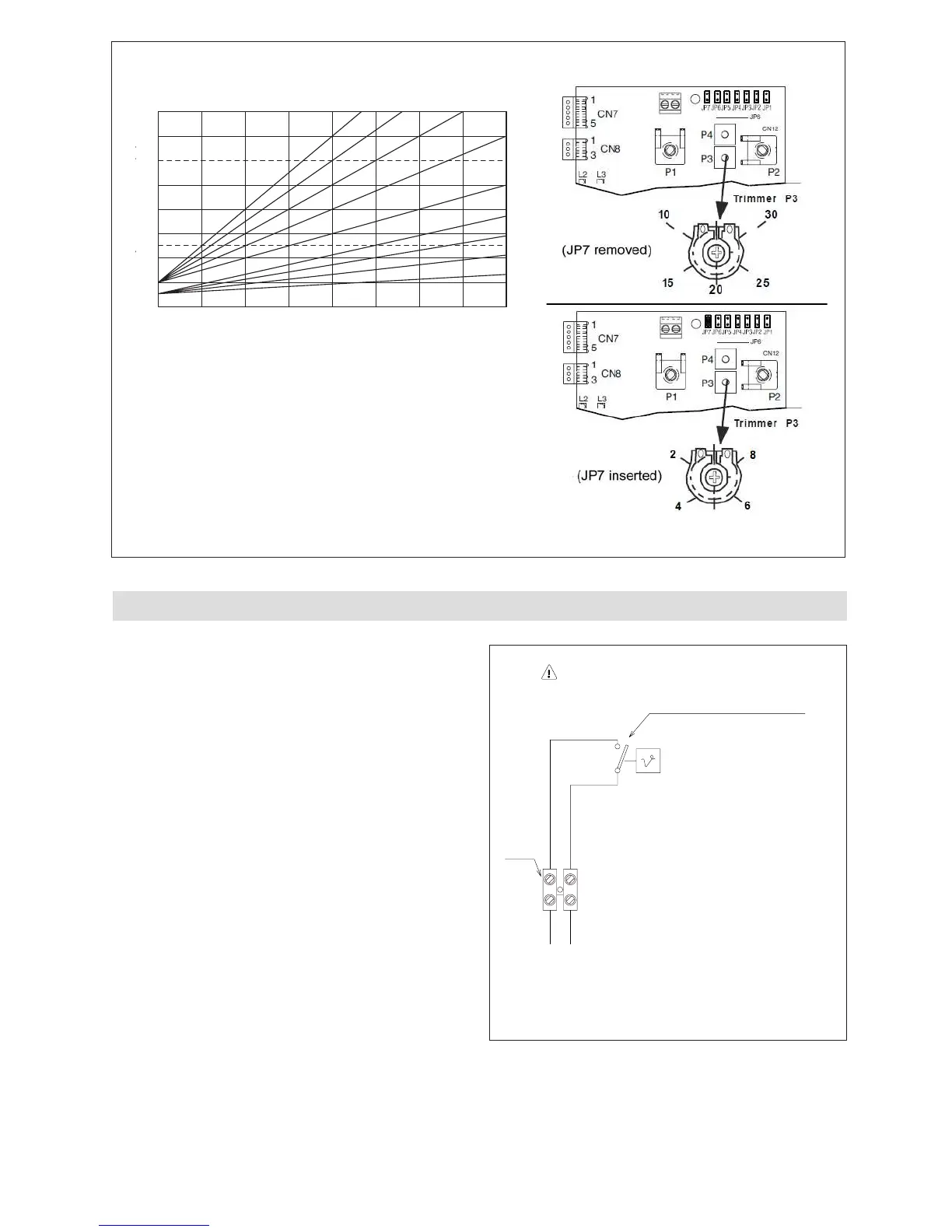
T80
T45
-15-10-505101520
CLIMATIC CURVES
EXTERNAL TEMPERATURE (°C)
FLOW OUTLET TEMPERATURE (°C)
T80 Maximum set point for standard T range (JP7 removed)
T45 Maximum set point for low T range (JP7 inserted)