VOLCANO VR Mini
VOLCANO VR1
VOLCANO VR2
VOLCANO VR3
VOLCANO VR-D
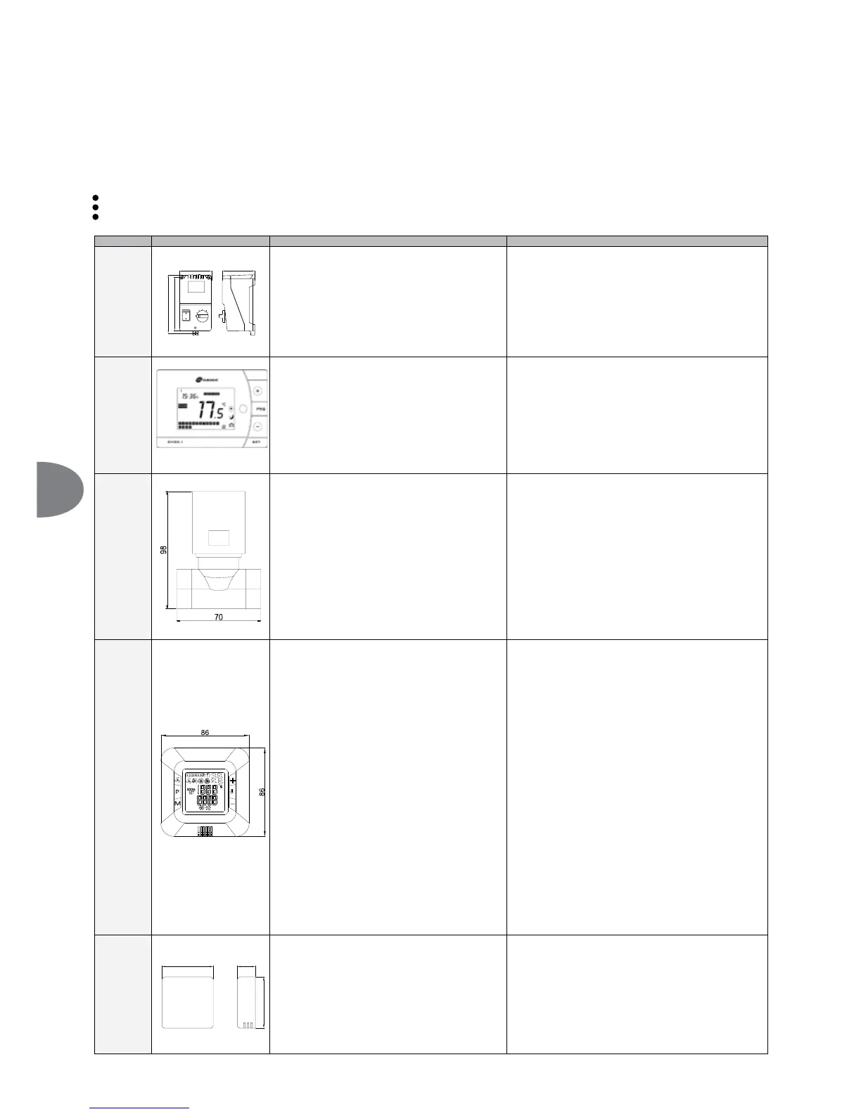
5. AUTOMATICS
5.1 ELEMENTS OF AUTOMATICS
(OHFWULFFRQQHFWLRQVPD\RQO\EHPDGHE\ZHOOWUDLQHGHOHFWULFLDQVDQGDFFRUGLQJWR
Occupational health and safety regulations
Assembly instructions
Technical documentation for each of the automatic elements
NOTE Before starting the assembly process and connecting the system, familiarize yourself with the original documentation attached to the automatic devices.
MODEL DIAGRAM TECHNICAL DATA COMMENTS
ARW 3,0/2*
(Volcano VR Mini, VR1,
VR2, VR3, VR-D)
VTS: 1-4-0101-0434
90
91
164
145
SPEED CONTROLLER – ARW 3,0/2
Ɣ 3RZHUVXSSO\YROWDJH9$&
Ɣ $OORZDEOHFXUUHQWRXWSXW$
Ɣ &RQWUROPRGHVWHSFRQWURO
Ɣ 1XPEHURIFRQWUROOHYHOV
Ɣ 7\SHRISURWHFWLRQ,3
Ɣ $VVHPEO\PHWKRGV2QDZDOO
Ɣ :RUNHQYLURQPHQWSDUDPHWHUV«&
Ɣ Do not connect more than one VOLCANO VR 1/VR 2/VR 3/VR-D
device to one rotation controller and more than four
VOLCANO VR Mini devices due to the values of permissible
output currents.
Ɣ Minimal distance between particular fans installed – both vertical
and horizontal – 20 cm.
Ɣ We recommend the execution of power supply connection with a
min. 3 x 1.5mm
2
wire
Ɣ Automation element drawings present the visualizations of model
products only.
EH20.1
VTS: 1-4-0101-0039
134mm x 94mm x 28mm
PROGRAMMABLE TEMPERATURE CONTROLLER
Ɣ
Power supply: alkaline battery 1.5 V (included)
Ɣ
6HWWLQJUDQJH«&
Ɣ
Setting and indications resolution: 0.5°C
Ɣ
3HUPLWWHGFRQWURORXWSXWORDG$«9$&
Ɣ
Type of protection: IP30
Ɣ
Assembly methods: on a wall
Ɣ
:RUNHQYLURQPHQWSDUDPHWHUV«&
Ɣ
Work cycle switching time: 60 min
Ɣ
Programmer: with weekly clock
Ɣ
Operation mode: Manufacturer or custom settings
Ɣ
Detailed description of the programmable temperature regulator, see
manual at www.vtsgroup.com
Ɣ
Thermostat and programmable temperature regulator should be
installed in a visible location.
Ɣ
Avoid places directly exposed to solar radiation, electromagnetic
waves, etc.
Ɣ
Power connection should be done with a cable min. 2 x 0.75 mm
2
.
Ɣ
The automation element drawings are only a visualization of sample
products.
TWO-WAY VALVE WITH VR ACTUATOR VR
VTS: 1-2-1204-2019
TWO-WAY VALVE
Ɣ
Connection diameter: 3/4”
Ɣ
Operation mode: on/off
Ɣ
Maximum differential pressure 90 kPa
Ɣ
Pressure degree PN 16
Ɣ
$LUÀRZGHJUHHIDFWRUNYVP
3
/h
Ɣ
Maximum heat agent temperature: 105°C
Ɣ
Work environment paramet ers: 0-60°C
VALVE ACTUATOR
Ɣ
Power consumption 7 VA
Ɣ
3RZHUVXSSO\YROWDJH9$&
Ɣ
Closing/opening time 4-5/9-11s
Ɣ
Item without supply: closed
Ɣ
Type of protection: IP54
Ɣ
Work environment parameters: 0-60°
Ɣ
Two-way valve should be installed on the return (outlet) pipeline.
Ɣ
Automation element drawings are only a visualisation of sample
products.
Ɣ
Power connection should be done with a cable min. 2 x 0.75 mm
2
.
Ɣ
Automation element drawings are only a visualisation of sample
products.
HMI VR (VTS: 1-4-0101-0169)
HMI VR CONTROLLER for ARWE3.0 regulator
Ɣ SRZHUVXSSO\a9+]
Ɣ maximum output current for valve or valves with actuator:
3(1)A
Ɣ power consumption: 1.5VA
Ɣ temperature set-up range: 5~40°C
Ɣ parameters of the working conditions: 5~50°C
Ɣ relative humidity: 0,85
Ɣ display: gray, blue backlight
Ɣ built-in sensor: NTC 10K, 3950 Ohm at 25°C
Ɣ outside sensor: option to connect the outside NTC sensor
Ɣ accuracy of measurement: + 1°C (measurement every +0.5°C)
Ɣ weekly calendar scheduling: 5+1+1
Ɣ operating mode: heating/cooling
Ɣ FRQWURORSWLRQVDXWRPDWLF9PDQXDO
Ɣ clock: 24h
Ɣ displayed temperature: room temperature or set temperature
Ɣ programming of heating/cooling: two periods of heating per
24h (5+1+1) or continuous operation
Ɣ anti-frost protections: valve opening due room temperature
drop below 8°C
Ɣ ingress protection rating: IP30
Ɣ PRXQWLQJPHWKRGÀXVKPRXQWHGER[¿PP
Ɣ operating: external keyboard
Ɣ QXPEHURIVHUYHG$5:(UHJXODWRUV
Ɣ maximum length of the signal cable: 120m
Ɣ FDVLQJ$%68/¿UHUHWDUGDQWSODVWLF
Ɣ colour: RAL 9016
Ɣ dimensions/weight: 86x86x54mm/0.12kg
Ɣ external communication: RS485 (MODBUS)
Ɣ suggested diameter of supply cable: 2x1mm2
Ɣ Detailed description of the programmable temperature regulator, see
manual at www.vtsgroup.com
Ɣ Thermostat and programmable temperature regulator should be
installed in a visible location.
Ɣ Avoid places directly exposed to solar radiation, electromagnetic
waves, etc.
Ɣ The automation element drawings are only a visualization of sample
products.
NTC.TEMP f
or HMI VR controller
(VTS 1-2-1205-1008)
Room NTC sensor for HMI VR controller
Ɣ resistant sensing element: NTC 10K
Ɣ ingress protection rating: IP20
Ɣ mounting method: wall mounted
Ɣ maximum length of the signal cable: 100m
Ɣ parameters of the working conditions: 0..40C
Ɣ accuracy of the measurement: 0.5K (10 ~ 40C)
Ɣ temperature measurement range: -20...+70C
Ɣ dimensions/weight: 74x74x26mm/0.1kg
Ɣ suggested diameter of supply cable (shielded cable):
2x0,5mm2
Ɣ NTC temperature sensor should be installed in the representative
location
Ɣ Avoid places directly exposed to sunlight, electromagnetic waves
etc.
Ɣ The automation element drawings are only a visualisation of sample
products
36
EN
 Loading...