Do you have a question about the VOLTCRAFT 632 FG and is the answer not in the manual?
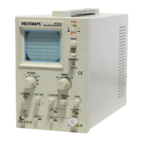
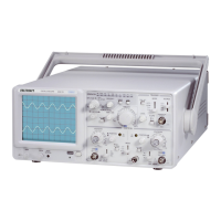
Overview of the VOLTCRAFT 632FG oscilloscope and function generator's capabilities and design.
Details key features like high intensity CRT, wide bandwidth, sensitivity, and various triggering modes.
Instructions for unpacking and inspecting the instrument for any shipping damage.
Guidance on setting the correct line voltage and ensuring proper grounding for safety.
Recommendations for operating the instrument within specified ambient temperature and avoiding magnetic fields.
Ensuring proper ventilation and operation according to specifications to maintain instrument protection.
Advises against excessive CRT trace brightness or prolonged spot display to prevent phosphor damage.
Specifies maximum input voltages for various terminals to prevent damage.
Detailed description of controls and connectors on the front panel of the oscilloscope.
Identification of input/output terminals, power connector, and fuse/voltage selector on the rear panel.
Step-by-step guide for setting up and operating the oscilloscope for single-channel measurements.
Instructions for displaying and operating with two input channels simultaneously.
Explains how to display the algebraic sum of CH1 and CH2 signals.
Detailed explanation of trigger modes, sources, level control, and slope selection for stable waveforms.
Guidance on selecting sweep time ranges for optimal waveform display and resolution.
How to use the x10 MAG function to expand specific parts of the waveform for detailed analysis.
Procedure for using the oscilloscope in X-Y mode for plotting one signal against another.
Steps to properly compensate the oscilloscope probe for accurate measurements.
Method for adjusting the vertical axis balance for accurate DC level measurements.
Overview of the integrated function generator controls for waveform, amplitude, and DC level.
Procedure for replacing the fuse, including safety warnings and correct fuse specifications.
Instructions on how to change the line voltage setting and corresponding fuse for different power sources.
Guidelines for cleaning the instrument safely, avoiding harsh chemicals and abrasives.
| Type | Function Generator |
|---|---|
| Output Impedance | 50 Ω |
| Display | LCD |
| Waveforms | Sine, Square, Triangle, Pulse, Ramp, DC |
| Dimensions | 230 mm x 95 mm x 280 mm |