16
5-8 Calibration of Probe
As explained previously, the probe makes up a wide range attenuator. Unless phase compensation is properly done, the
displayed waveform will be distortion causing measurement errors. Therefore, the probe must be properly compensated
before use. Connect 10:1 probe BNC to the INPUT terminal of CH1 or CH2 and set VOLTS/DIV switch at 50mV.
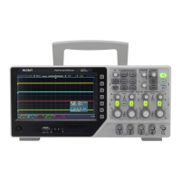
Connect the probe tip to the calibration voltage output terminal and adjust the compensation trimmer on probe for
optimum Square wave (minimum overshoot, rounding off and tilt).
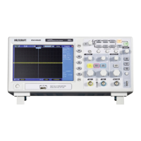
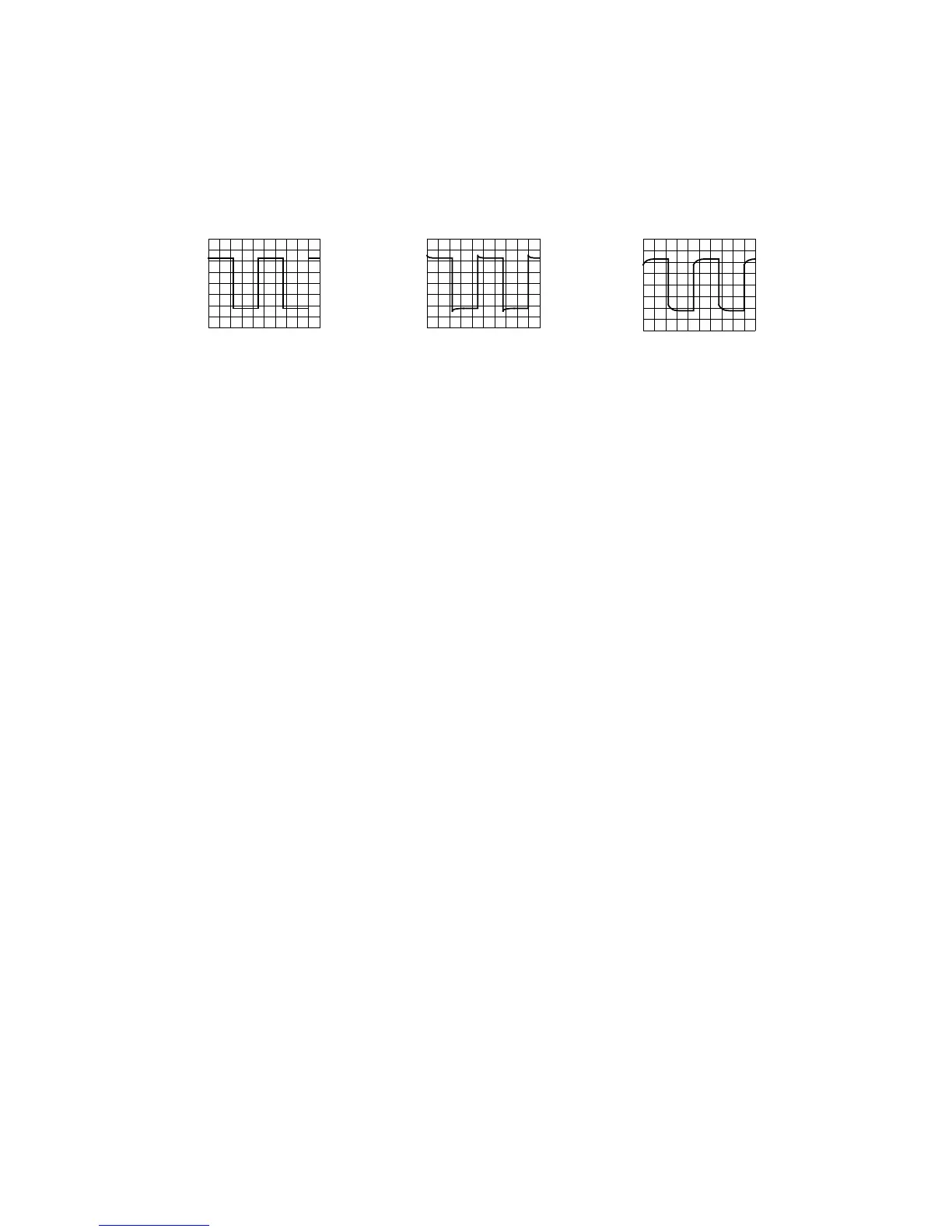
FIG. 5-7
(a) Correct compensation
(b) Over compensation
(c) Insufficient compensation
5-9 DC BAL Adjustments
The ATT balance of the vertical axis can be adjusted easily.
(1) Set the input coupling switches of CH1 and CH2 to GND and set the TRIG MODE to AUTO, then position the
base line to the center.
(2) Adjust the VLOTS/DIV switch to 5mV-10mV and fix the line does not move.
5-10 Function Generator
The instrument also provides the basic features of Function Generator to satisfy general demand with simply and
intuitional operation method by adjusting the control knobs directly from front panel for output waveform, amplitude,
DC level and etc. All the control knobs located in front panel are marked with the same color to prevent missetting.