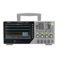
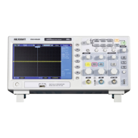
7
3. PRECAUTIONS BEFORE OPERATION
3-1 Unpacking the instrument
The product has been fully inspected and tested before shipping from the factory. Upon receiving the instrument,
please unpack and inspect it to check if there is any damage caused during transportation. If any sign of damage is
found, notify the bearer and/or the dealer immediately.
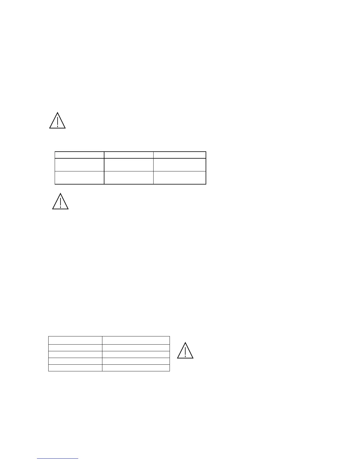
3-2 Checking the Line Voltage
The product can be applied any kind of the line voltage shown in the table below. Before connecting the power plug
to an AC line outlet, make sure the voltage selector of the rear panel is set to the correct position corresponding to the
line voltage. It might be damaged the instrument if connected to the wrong AC line voltage.
WARNING. To avoid electrical shock, the power cord protective grounding conductor must be
connected to ground.
The fuse must be changed following after the line voltage shown as below:
Line voltage Range Fuse
AC 115V 97~132V
T 0.63A
250V
AC 230V 195~250V
T 0.315A
250V
WARNING. To avoid personal injury, disconnect the power cord before removing the fuse holder.
3-3 Environment
The normal ambient temperature range of this instrument is from 0° C to 40°C (32°F to 104°F). To operate the
instrument over this specific temperature range may cause damage to the circuits.
Do not operate the instrument in a place where strong magnetic or electric field exists as it may disturb the
measurement.
3-4 Equipment Installation and Operation
Ensure there is proper ventilation for the vent of the instrument. If it is not according to the specification to operate
the instrument, the protection provided by the instrument may be impaired.
3-5 CRT Intensity
To prevent permanent damage to the CRT phosphor, do not let the CRT trace brighten excessively or leave the spot
stay for an unreasonable long time.
3-6 Withstanding Voltages of Input Terminals
The withstanding voltages of the instrument input terminals and probe input terminals are shown in the following
table. Do not apply voltage higher than the specification. When set probe switch at 1: 1, the maximum effective
readout is 40Vp-p (14Vrms at Sine wave), set probe switch at 10: 1, the maximum effective readout is 400Vp-p
(140Vrms at Sine wave).
Input terminal
Maximum input voltage
CH1, CH2, inputs 300Vpeak
EXT TRIG IN input 300Vpeak
Probe inputs 600Vpeak
Z AXIS input 30Vpeak
CAUTION. To avoid an