5
2. TECHNICAL SPECIFICATIONS
MODEL
SPECIFICATIONS
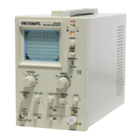
VOLTCRAFT 632FG
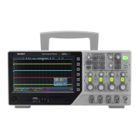
30MHz OSCILLOSCOPE + FUNCTION GENERATOR
1. OSCILLOSCOPE
Sensitivity 5mV ∼ 5V/DIV, 10 steps in 1-2-5 sequence.
Sensitivity Accuracy ≤3% ( × 5 MAG : ≤5%).
Vernier Vertical sensitivity
To 1/2.5 or less of panel-indicated value.
DC∼30MHz ( × 5MAG: DC∼7MHz).
Frequency bandwidth
AC coupling: Low limit frequency of 10Hz.
(With reference to 100kHz, 8DIV. Frequency response at -3dB).
Rise time Approx. 11.6nS (×5 MAG: Approx. 50nS).
Input impedance Approx. 1M ohm // Approx. 25pF.
Square Wave Characteristics
Overshoot : ≤ 5% ( At 10mV/DIV range).
Other distortions and other ranges: 5% added to the above value.
DC Balance Shift Panel adjustable.
Linearity
<±0.1DIV of amplitude change when waveform of 2 DIV at graticule center is moved
vertically.
Vertical modes
CH1 : CH1 single channel.
CH2 : CH2 single channel.
DUAL : CH1 and CH2 are displayed. ALT or CHOP selectable at any sweep rate.
ADD : CH1 + CH2 algebraic addition.
Chopping Repetition
Frequency
Approx. 250kHz.
Input Coupling AC, GND, DC.
Maximum Input Voltage
300Vpeak (AC: frequency 1kHz or lower).
Set probe switch at 1: 1, the maximum effective readout is 40Vpp (14Vrms at Sine wave),
set probe switch at 10: 1, the maximum effective readout is 400Vpp(140Vrms at Sine wave).
Common Mode Rejection
Ratio
50:1 or better at 50kHz sinusoidal wave. (When sensitivities of CH1 and CH2 are set
equally).
Isolation between channels
(At 5mV/DIV range)
>1000:1 at 50kHz.
>30:1 at 30MHz.
CH1 signal output At least 20 mV/div into a 50Ωterminal, Bandwidth is 50Hz to 5MHz at least.
VERTICAL
AXIS
CH2 INV BAL. Balanced point variation: ≤1 DIV (Reference at center graticule).
Triggering source
CH1, CH2, LINE, EXT (CH1 and CH2 can be selected only in the DUAL or ADD vertical
mode).
In ALT mode, if the TRIG. ALT switch is pushed in, it can alternate triggering of two
different source.
Coupling AC: 20Hz to full bandwidth.
Slope + / -.
Sensitivity
20Hz ∼ 2MHz : 0.5 DIV, TRIG-ALT:2 DIV, EXT : 200mV.
2 ∼ 30MHz : 1.5 DIV, TRIG-ALT:3 DIV, EXT : 800mV.
TV : Sync pulse more than 1 DIV (EXT: 1V).
Triggering modes AUTO : Sweeps run in the free mode when no triggering input signal is applied.
(Applicable for repetitive signals of frequency 25Hz or over.).
NORM : When no triggering signal is applied, the trace is in the ready state, but not
displayed.
TV-V : This setting is used when observing the entire vertical picture of television signal.
TV-H : This setting is used when observing the entire horizontal picture of television
signal.
(Both TV-V and TV-H synchronize only when the synchronizing signal is negative)
EXT Triggering Signal Input
Input Impedance Approx.: 1M ohm // approx. 25pF.
TRIGGERING
Max. Input Voltage 300V (DC+AC peak), AC: Frequency not higher than 1kHz.