TAMD71B
Control panel for auxiliary control position (Flying Bridge)
Cable areas in mm
2
are given after the color codes in the wiring diagrams.
The cable area is 1.5 mm
2
unless otherwise stated.
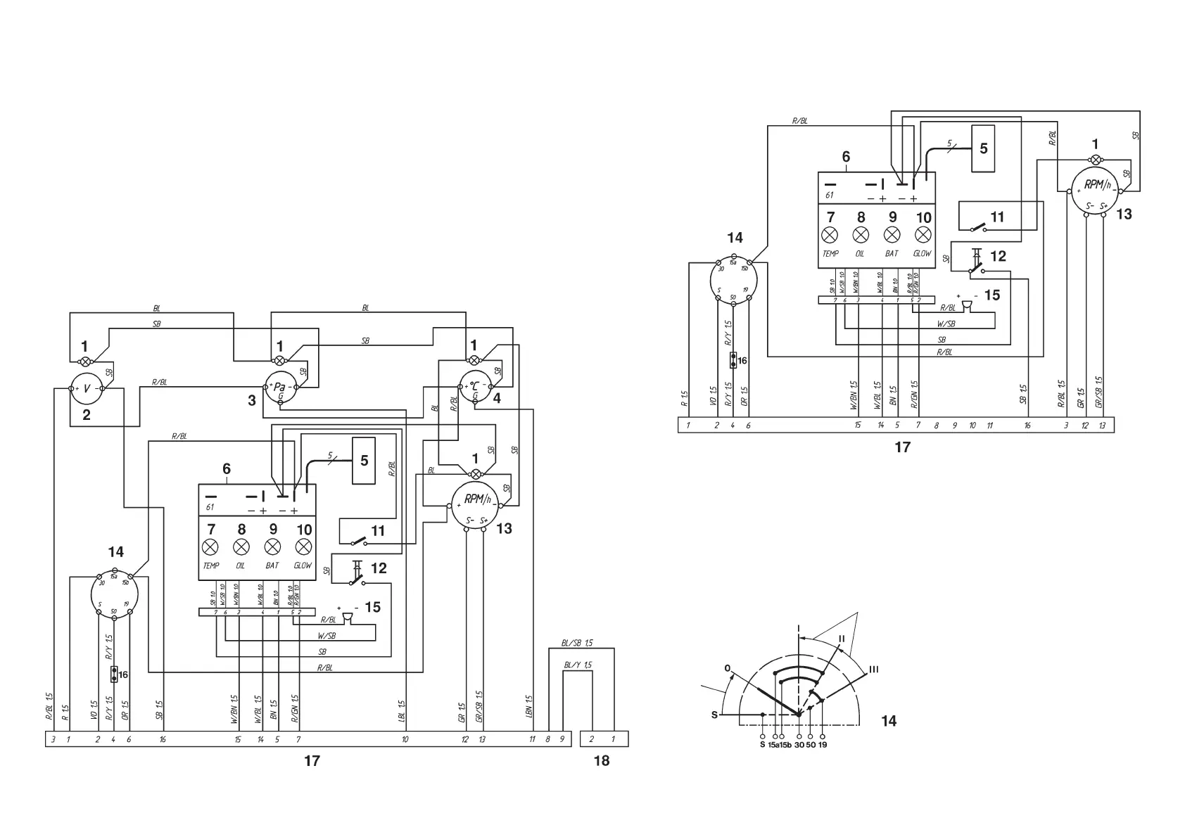
Instrument panel, (Master panel)
Spring loaded
Spring loaded
Instrument panels
1. Instrument lighting
2. Voltmeter
3. Oil pressure gauge
4. Engine coolant temperature gauge
5. Connector for extra
warning display (accessory)
6. Electronics module (alarm)
7. Engine coolant temperature warning lamp
8. Oil pressure warning lamp
9. Charge warning lamp
10. Control lamp, pre-heating
11. Switch, instrument panel lighting
12. Alarm test/acknowledgement switch
13. Tachometer with built-in hours run
meter
14. Key switch
15. Alarm
16. Connector for connecting neutral
position switch, if fitted (accessory)
17. 16-pin connector
18. 2-pin connector (for auxiliary panel
where installed)
7740156 - Downloaded from www.volvopenta.com 22/07/2009 00:44:08
 Loading...