93
TAMD74
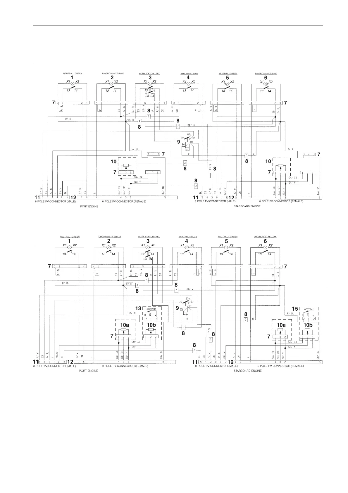
Electronic control
Twin engine installation. Single lever twin control
Mechanical control
Twin engine installation. Single or dual lever twin control with control unit adapter
Cable colors
BL = Blue
BN = Brown
GN = Green
OR = Orange
P = Pink
R = Red
SB = Black
W = White
Y = Yellow
Cable areas = 0.75 mm
2
.
Location diagram (both wiring diagrams)
1. Push button with indicator light,
Neutral – green
2. Push button with indicator light,
Diagnostic – yellow
3. Push button with indicator light,
Active station – red
4. Push button with indicator light,
Synchro – blue
5. Push button with indicator light,
Neutral – green
6. Push button with indicator light,
Diagnostic – yellow
7. Connector
8. Connector, Port – Starboard cable harness
9. Relay
10. Potentiometer, throttle/shifting
10a. Control unit adapter, throttle
10b. Control unit adapter, shifting
11. 8-pin connector (male) – port engine
12. 8-pin connector (female) – starboard
engine
13. Neutral switch
7740156 - Downloaded from www.volvopenta.com 22/07/2009 00:44:08