92
TAMD74
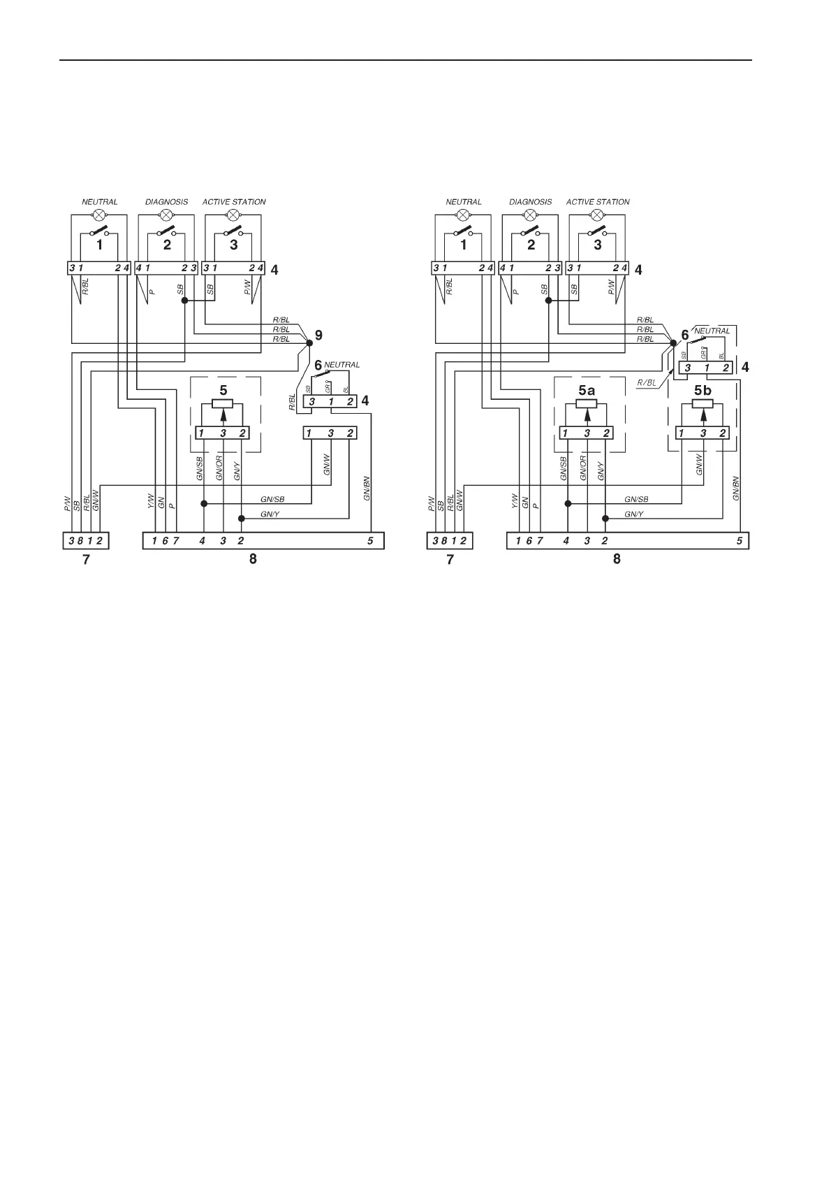
Electronic control
Single engine installation.
Single or dual control lever unit
Mechanical control
Single engine installation. Single or dual control
lever unit with control unit adapters
Cable colors
BL = Blue
BN = Brown
GN = Green
OR = Orange
P = Pink
R = Red
SB = Black
W = White
Y = Yellow
Cable areas = 0.75 mm
2
.
Location diagram
1. Push button with indicator light, neutral – green
2. Push button with indicator light, diagnostic – yellow
3. Push button with indicator light, active station – red
4. Connector
5. Potentiometer, throttle/shifting
5a. Control unit adapter, throttle
5b. Control unit adapter, shifting
6. Neutral switch
7. 8-pin connector (male)
8. 8-pin connector (female)
9. Joint splice
7740156 - Downloaded from www.volvopenta.com 22/07/2009 00:44:08
 Loading...