91
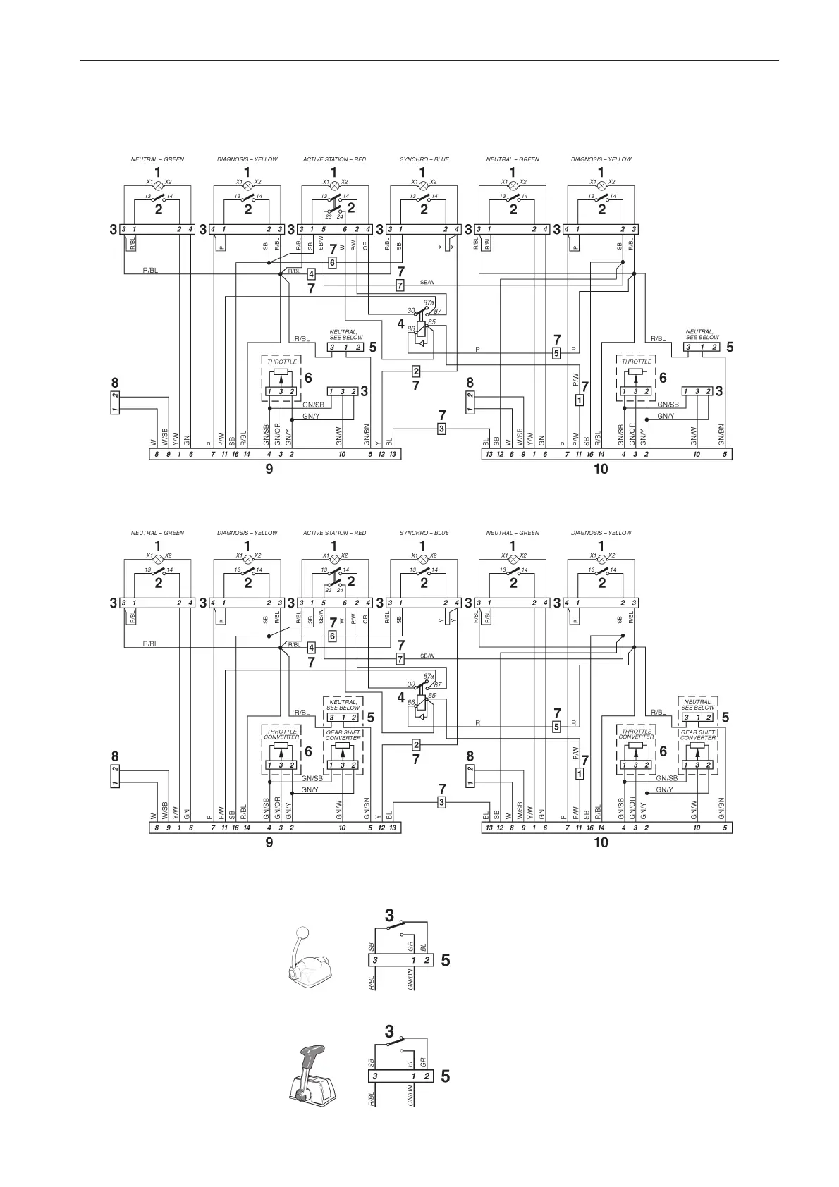
Multiple control positions – Single or dual lever controls (twin engine installation)
Multiple control positions – Single or dual lever controls with control adapters (twin engine installation)
Cable color
BL = Blue
BN = Brown
GN = Green
OR = Orange
P = Pink
R = Red
SB = Black
W = White
Y = Yellow
Cable areas = 0.75 mm
2
.
Location diagram (both wiring diagrams)
1. Indicator light
2. Switch
3. Connector
4. Relay
5. Position limiter switch
6. Potentiometer
7. Connector, Port – Starboard cable harness
8. 2-pin connector, data link connector (DLC)
9. 16-pin connector, Port engine
10. 16-pin connector, Starboard engine
TAMD73P-A
VP controls:
Late model
NEUTRAL
Early model
NEUTRAL
7740156 - Downloaded from www.volvopenta.com 22/07/2009 00:44:08
 Loading...