VOLVOTECH.EU INSTALLATION MANUAL
VBB4 ( VIDEO BREAK- IN BOX TYPE 4) VERSION 1.1
Page 4 of 14
CopyRight 2012, VolvoTech.EU
C: BE || CD 121107 || V 1.00 || RD 140228 || HC 1 || FC 3.26 ||
VolvoTech-manual-EN-installation-VBB4-VID-POW-MC-S40-V50-
C70-1.1.doc
Contact details:
VolvoTech.EU
support@volvotech.eu
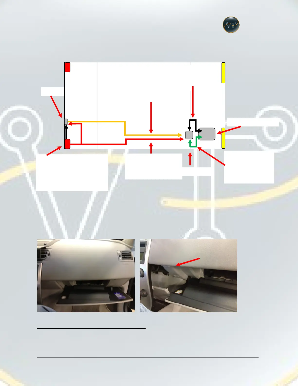
SCHEMATIC OVERVIEW OF COMPONENTS AND WIRING.
INSTALLATION
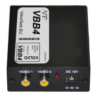
VBB4 (Video Break-in Box type 4)
Open glove compartment. Remove panel behind the console.
From Camera to
VBB4 (RCA/RCA
Provides 12V+ and 12V- to
the camera and VBB4 when
car in reverse. (Right is more
easy since RTI compu is ont
reverse light.
(Connects to the
harness from VBB4
to RTI computer
harness from VBB4
to RTI computer
(Power)