VA10800/VA10820 Evaluation Board User’s Manual
V3.0
3
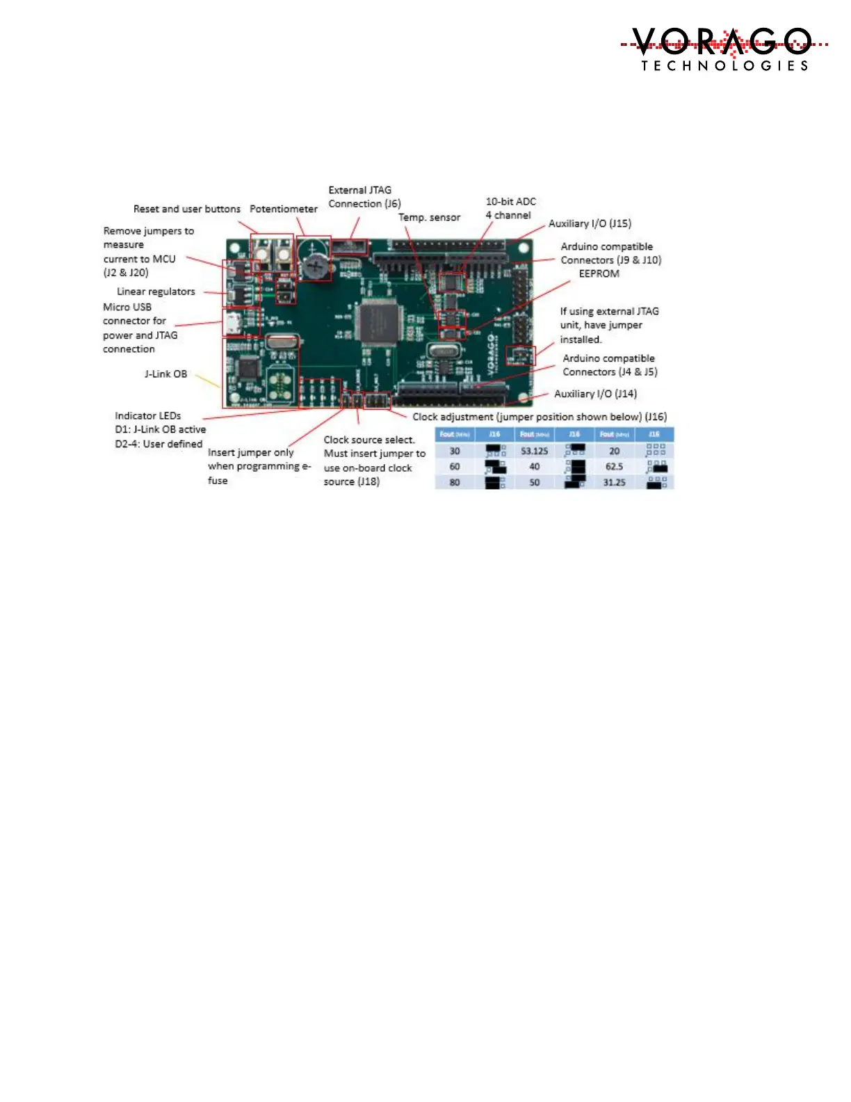
1.3 REB1 board component placement diagram
Figure 2 - Photo of REB1 with functional blocks identified
1.4 Connector pin assignment table
The schematic for the board is one of the included files in the REB1 software download
package. To assist with quickly finding which pins are tied to the various connectors on the
board, the following set of tables are provided.
 Loading...