EasyManua.ls Logo

Voxx Electronics 18LCDSP - User Manual

Voxx Electronics 18LCDSP
2 pages
Print Icon
To Next Page IconTo Next Page
Loading...
1
2
3
4
1 2 3 4
1
2
3
4
1 Red/Black
Ignion 3 Flex Relay (87) Input
2 Pink
Ignion 3 Flex Relay (30) Output
3 Yellow
Starter Output (+)
4 Green
Ignion 2 Output (+)
5 Red
Baery 12V (+)
6 Red/White
Baery 12V (+)
7 Purpl e
Accessory Output (+)
8 Blue
Ignion 1 Input / Output (+)
8 Pin Start
P
P
P
1 White
Parking Light (30) Output
2 White/Red
Parking Light (87) Input
3 White/Black
Siren Output (+)
4 Black
Ground Input (-)
4 Pin Light
P
1
White Data RX
2
Black Ground (-)
3 Blue
Data TX
4 Red
BaƩery 12V (+)
DBI
1
White Data RX
2
Blue Data TX
3 Black
Ground (-)
4 Red
BaƩery 12V (+)
RF
1
Blue Data TX
2
White Data RX
3 Black
Ground
4 Red
BaƩery 12V (+)
Carlink
4 Red
BaƩery 12V (+)
3 Black
Ground (-)
2
Blue Data TX
1
White Data RX
Weblink
22
Green
Unlock Output (-) (NOC 11)
21
Dk. Blue
Trunk Output (-) (NOC 9)
20 Red Lock Output (-) (NOC 10)
19 Green/Lt. Blue Ch. 4 AUX Output (-) (NOC 8)
18 Black/White Horn Output (-)
17 Lt. Blue/Green Ch. 5 AUX Output (-) (NOC 7)
16 Red/Black 2nd Unlock Output (-) (NOC 12)
15
Black/Lt. Green
Factory Arm Output (-) NOC 6)
14 Brown/Black Brake Input (+) (PIC 6)
13 Black/Blue Factory Disarm Output (-) (NOC 5)
12 Dk. Blue/Black External Acvaon Input (-) (PIC 5)
11 Black/Red Pulse Aer Shutdown Output (-) (NOC 4)
10 Orange/Black Parking Brake Input (-) (PIC 4)
9 Black/Yellow Pul se During Crank Output (-) (NOC 3)
8 Green/Yellow Diesel Glow Plug Input (+) (PIC 3)
7 Green/White DomeLight Output (-) (NOC 2)
6 Purple/Brown Door Tri gger Input (- /
+)
5 Lt. Blue Remote Start Status Output (-) (NOC 1)
4 Green/Orange Tach Input (-)
3 Gray/Black Hood Input (-) (PIC 2)
2 Lt. Green Trunk Trigger Input (-) (PIC 1)
1 Orange Starter Kill Relay / An-Gri nd Output (-)
22 Pin Input/Output
4 Red
BaƩery 12V (+)
3 Black
Data TX
2
Blue Warn Away
1
Green Full Trigger
Shock
1 2 3 4
VOXX
FLCART Dock
Replacement Part #4120459
Replacement Part #4120457
Replacement Part #4120462
Replacement Part #4120458
Not Included
Not Included
Not Included
Not Included
85 Red
IgniƟon Input (+)
86 Orange
Starter Kill Input (-)
87A
Black Starter Output - Motor Side
30
Black/White Starter Input - Key Side
Starter Kill
86
85
87
87A
30
Replacement Part #4360828
Replacement Part #4360830
This Harness is included with the FLCART.



Not Included
19
17
15
13
11
9
7
5
3
1 2
4
6
8
10
12
14
16
18
20
21 22
19
20
17 18
15
16
13
14
11 12
9
10
7 8
5 6
3 4
1 2
1 3 5 7
2 4 6 8
1 3
2 4
1
2
3
4
APS997Z
Security and Remote Start
System Layout
Shock Sensor
Part #4700033
4180075 18LCDSP 185SP
Important Update
The default Data Port Protocol of this system is ADS. If using an FLCAN or other external integraon
module be sure to choose iDatalink 2-Way when ashing.
This system will also support DBI. This will require programming Feature Bank 2, Feature 15 to DBI.
Question and Answer IconNeed help?

Do you have a question about the Voxx Electronics 18LCDSP and is the answer not in the manual?

Summary

System Layout Overview

Shock Sensor Connection

Details for connecting the shock sensor to the main unit, specifying wire colors and functions.

Main Input;Output Harness

Layout and pinout for the 22-pin main input/output harness of the APS997Z system.

Start and Light Harness Connections

Pinout details for the 8-pin start and 4-pin light harnesses, including ignition and parking light functions.

Data and Power Connections

Wiring information for data RX/TX, ground, and 12V+ power connections for various modules.

Starter Kill Switch Wiring

Wiring diagram for the starter kill relay, covering motor side and key side connections.

Important System Update

Critical information regarding default data port protocol and programming updates for integration modules.

Remote Programming Procedures

Remote Auto Programming

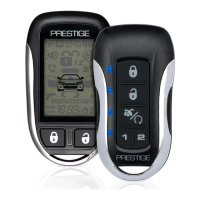
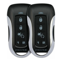
Steps to program new remotes to the APS997Z system using the valet button and lock function.

Feature Programming Guide

Feature Bank Programming

Instructions to access and configure system features across Feature Banks 1, 2, and 3 using valet button and lock.

System Notifications and Feedback

Alarm Trigger Notifications

System feedback for alarm triggers, indicating the zone of intrusion upon disarm.

Remote Start Failure Indications

Parking light flash patterns indicating specific reasons for remote start failure.

Customization and Control Features

Chirp Delete Functionality

Procedure to enable or disable system chirps for arming/disarming without entering feature banks.

User Programmable LED Control

Method to toggle the system's status LED notifications on or off.

Programmable Input Control Options

Configuration of Programmable Input Control (PIC) features via FlashLogic.

Negative Output Control (NOC) Options

Programming Negative Output Control (NOC) options via FlashLogic Weblink or Mobile.

AUX Output Control Configuration

Customizing any AUX output using the AUX Control Menu via FlashLogic.

Vehicle Specific Configuration

Tach Programming Procedure

Manual configuration of the engine confirmation method and tach rate for the system.

Data Protocol Selection

Automatic detection and configuration of data port protocols (ADS or DBI).

Dome Delay Programming

Setting the dome light delay feature to avoid false alarm triggers.

Voxx Electronics 18LCDSP Specifications

General IconGeneral
BrandVoxx Electronics
Model18LCDSP
CategoryRemote Starter
LanguageEnglish

Related product manuals