12
General:
1. Choose the monitor and camera loca
ons.
2. Install all required cables in vehicle. A 3/4”(19mm) hole should be drilled for
passing camera cables through vehicle walls, barriers, etc.
Install split grommets where applicable. If addi
onal cable on is required,
install convoluted tubing over the cable.
3.
cable/wiring has been routed and components are in place, temporarily
make all system conne
ons and perform a system f check. If the system
does not operate properly, see the
4. Make sure all cables are routed away from hot or moving parts and away from
sharp edges. Secure cables with wire
es.
Backup (Rear) Camera
Rear-mounted cameras used for monitoring
while backing up must be
connected to the CA1 input. Trigger#1 must be connected to the reverse gear
light circuit in the vehicle.
Side Camera
If side monitoring cameras are installed, they should be connected to either CA2
or CA3 inputs. Triggers 2 and 3 should be connected to the vehicle’s turn signal
circuits.
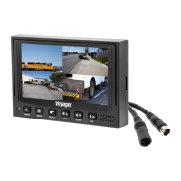
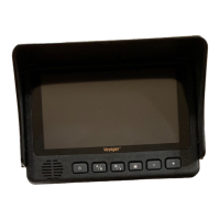
VOM74WP
Trouble ng
Blue Screen indicates No video signal. Check camera, cables, and all
connec
ons.