11
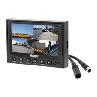
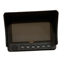
VOM74WP
Wiring Defini ons:
Power
Pin 1 POWER IN DC(12/24VDC) – RED
Pin 2 GROUND – Black
Pin 3 CHANNEL 1 TRIGGER – Blue
Pin 4 CHANNEL 2 TRIGGER – Brown
Pin 5 CHANNEL 3 TRIGGER – Green
Pin 6 CHANNEL 4 TRIGGER – Orange
Pin 7 AUDIO TRIGGER – White
Pin 8 SPLIT TRIGGER – Yellow
Camera 1 Input: 4-Pin
for camera or camera
extension cable
Camera 2 Input: 4-Pin
for camera or camera
extension cable
Camera 3 Input: 4-Pin
for camera or camera
extension cable
Camera 4 Input: 4-Pin
for camera or camera
extension cable
Installa on
BEFORE YOU BEGIN INSTALLATION:
Before drilling, be sure that no cable or wiring is on the other side. Clamp all wires
securely to reduce the possibility of them being damaged during in
and use.
Keep all cables away from hot or moving parts and electrically noisy components.