SERIES 1000-X ELECTRIC ACTUATORS
12VER: 0812-1
MOUNTING ON A VALVE
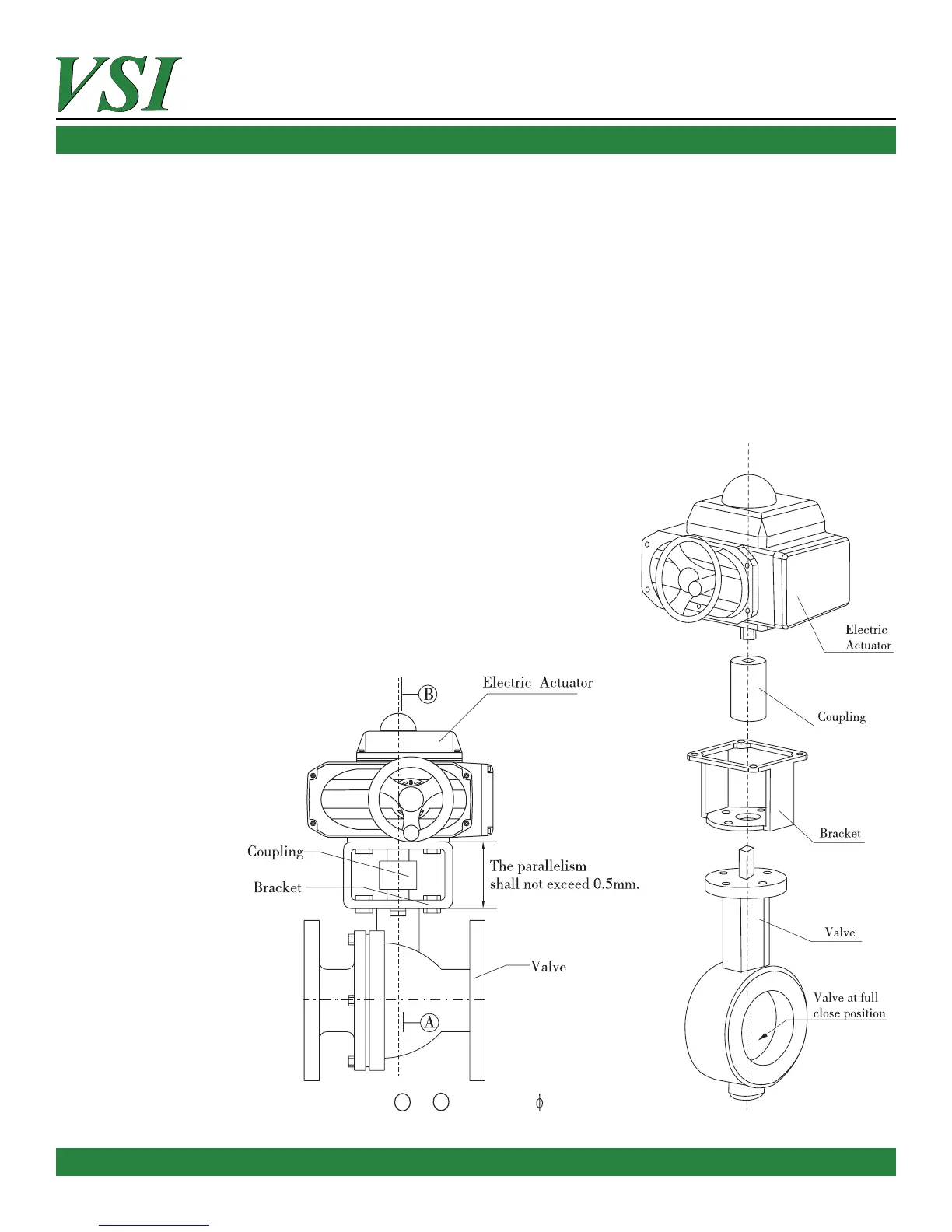
INSTALLATION OF ACTUATOR TO VALVE (FIG. 3)
Note: Direct mounting the actuator removes the bracket and coupling from the mounting process, but
the remainder remains the same.
1. Rotate valve to full closed posion. Ensure that the valve rotates freely with no obstrucon.
2. Using the proper bolts aach the bracket to the valve – ghten loosely.
3. Place the coupling onto the stem of the valve
4. Using the manual override handle, rotate the actuator to the full closed posion so that the pointer
indicator points to “SHUT” (stang posion of the scale).
5. Insert the output drive sha of the actuator into the coupling.
6. Aach bracket to actuator and ghten all bolts.
7. Drive the actuator using the manual crank handle and conrm that the valve rotates without obstruc-
on. Ensure the valve is fully open as the actuator rotates to full open posion.
Figure 3
Figure 4
Mounting Tips:
NOTE: This is not for direct mounting the actuator to the valve.
• If providing own bracket, ensure that the materials provided are
manufactured professionally and meet the requirements in Fig. 4.
• The precision of the coupling holes is crucial to prevent any
backlash or damage to the actuator.
• It is necessary to ensure the posional angles of the coupling
holes to prevent exceeding the actuator’s working range.
• Only ghten bolts aer the actuator, bracket and valve have
been properly aligned.
The coaxiality between axes A andBshall not exceed 0.2mm.


 To Next Page