+
+
+
+
+
+
+
+
+
R9
R109
C6
QC:
TEST:
+
+
+
FIL
FIL GND
B+
B+ GND
PCBA: 320-0628
P
C
B
:
3
6
0
-
0
6
2
5
-
2
0
0
V
E
R
2
.
0
U1
C6A
C106A
R8
R108
C9
C8
R1
R2
R4
R3
R101R102
R103
R104
R5
R6
R105
R106
R7
R107
R10
R12
R110
R112
R113
R13
R14
R14B
R13B
R17
R117
C106
C108
C109
C9A
C2
OUT
RIGHT
C109A
OUT
LEFT
C102
R114
C105
C101
R114B
C104
R113B
+
C5
C4
C1
MM IN
C3
C11
C12
C107
C103
+
++
RIGHT
LEFT
MC IN
MC IN
C112
C110
C109
C9
C10
C1A
C7
RIGHT
MM IN
LEFT
MC JP
MC JP
LEFT
RIGHT
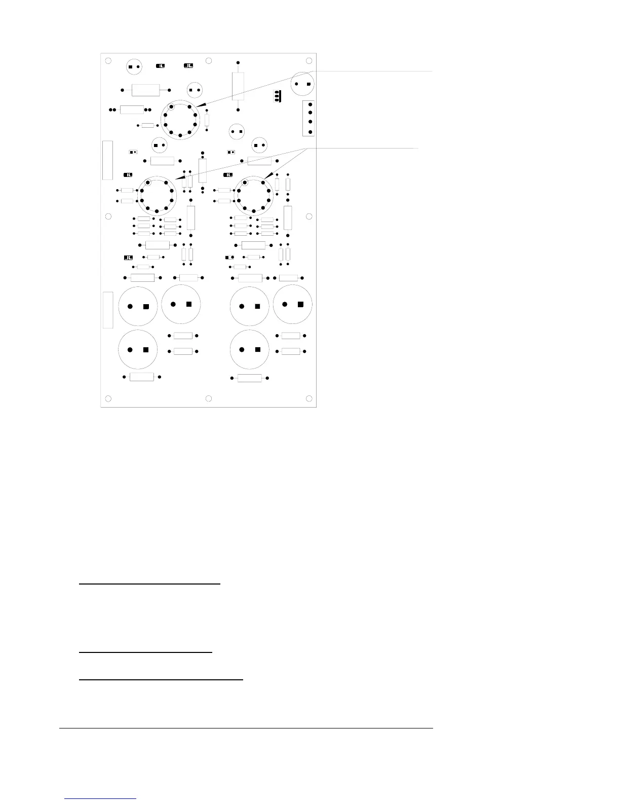
12AX7
V101 V1
12AX7
12AX7
V2
V1 and V101
use Sovtek 12AX7
in these locations
V2 use 12AX7 JJ
in these locations
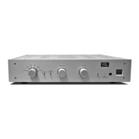
1. Remove the top cover of the TL2.5:
Turn off the TL2.5 preamp and remove the power cord. Use a #2 Phillips screw
driver and remove the 6 screws on the top and 2 screws on each side of the
preamplifier. Keep the screws in a safe place so that you can put the cover back
onto the unit when you have completed the following installation.
Check to make sure that the optional phono PC board is installed to the left of the
line stage PC board in your preamplifier. If you have any questions, please call
your dealer or the VTL factory for assistance.
2. Selecting MM
Jumpers on Phono PC Board: (near MM Input pads) There are two small
black jumpers located on the phono PC board near the left and right MM
Input pads. To set the phono stage for MM, lift the black pin jumper and
connect the jumper to one pin of the header only (does not matter which pin).
Do this for both headers (one per channel).
Tubes on Phono PC board: If you are using the phono board for MM only,
the tube in socket V2 can be removed.
Jumpers on RCA Input PC board: there are two sets of jumpers for
configuring the phono board to MM. Please change the connectors on the
TL2.5 Preamplifier Owner’s Manual
VTL
14
 Loading...