12
Installation
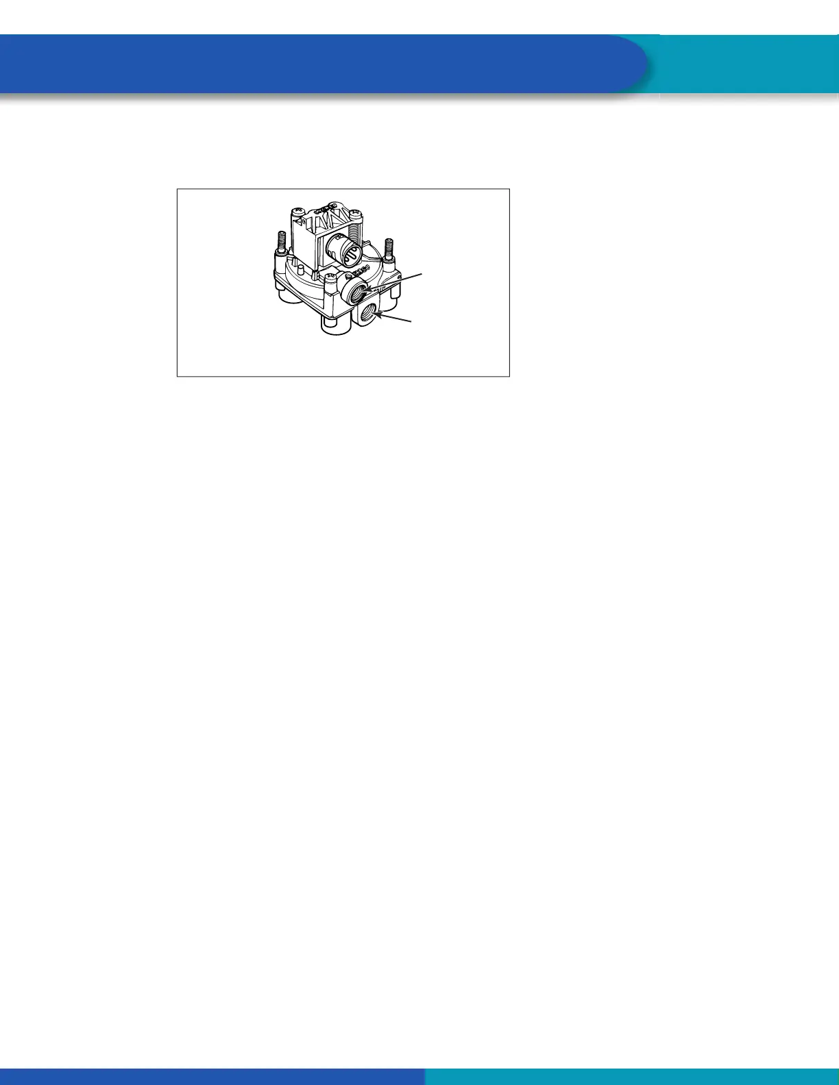
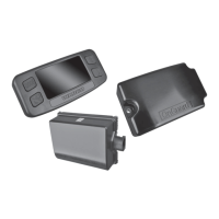
3. Rotate and tighten the relay valve assembly until the exhaust port faces down and the connection is
secure. Use a torque wrench or ratchet with an extension at the 3/4-inch pipe plug installed on the
front supply port. Figure 6.
Fig. 6
Exhaust
port must
face DOWN.
PLUG
UNUSED
PORTS
ABS EXTERNAL MODULATOR VALVE
CONTROL
PORT 4
SUPPLY
PORT 1
1002073d
5.1.5 Mounted to Cross Member of Vehicle (Mounting Bracket Not Supplied)
When mounting the relay valve assembly to the trailer cross member, refer to SAE specifi cation J447,
Prevention of Corrosion of Motor Vehicle Body and Chassis Components. Follow all recommendations and
procedures.
1. Install a 3/4-inch NPTF fi tting in the supply port. Use a 3/4-inch NPTF pipe plug to plug the unused
supply port (Port 1). Apply SAE-standard, DOT-approved sealing paste to either the fi rst few threads
or over the whole length. Pipes with pre-applied thread sealant may also be used.
2. Install the valve with two locknuts and washers as required. Tighten the locknuts to 18 lb-ft
(24 Nm).
5.1.6 Connect the Air Lines
Before connecting the air lines, plumb the spring brake relay or emergency brake relay into the system as
usual.
If you are mounting on a bracket, connect the air supply line from the supply tank to the supply
Port 1. Plug the unused port.
Use 5/8-inch O.D. min. nylon tubing or heavy-walled Schedule 80 pipe nipple (3/4-inch NPTF) if
you are mounting directly to the supply tank.
1. Connect the air delivery lines to the ECU/dual modulator valve assembly Port 2. For 4S/3M
installations, connect the air delivery lines to Port 2 on the external relay valve (3/8-inch NPTF).
2. Connect the air delivery lines to the appropriate brake chambers (3/8-inch NPTF). Figure 16.
The valve portion of the ECU/dual modulator valve assembly contains two separate valves: one
dedicated to roadside wheel ends, the other dedicated to curbside wheel ends. Each valve has
three delivery ports.
The external relay valve is an axle control valve. It controls brake chambers on one or two axles.
It is important that delivery lines from Port 2 are plumbed as shown. Refer to Figure 12 through
Figure 18.
3. Connect the brake service (control) line to the ECU/dual modulator valve assembly Port 4 (3/8-inch
NPTF).