32
Appendix I
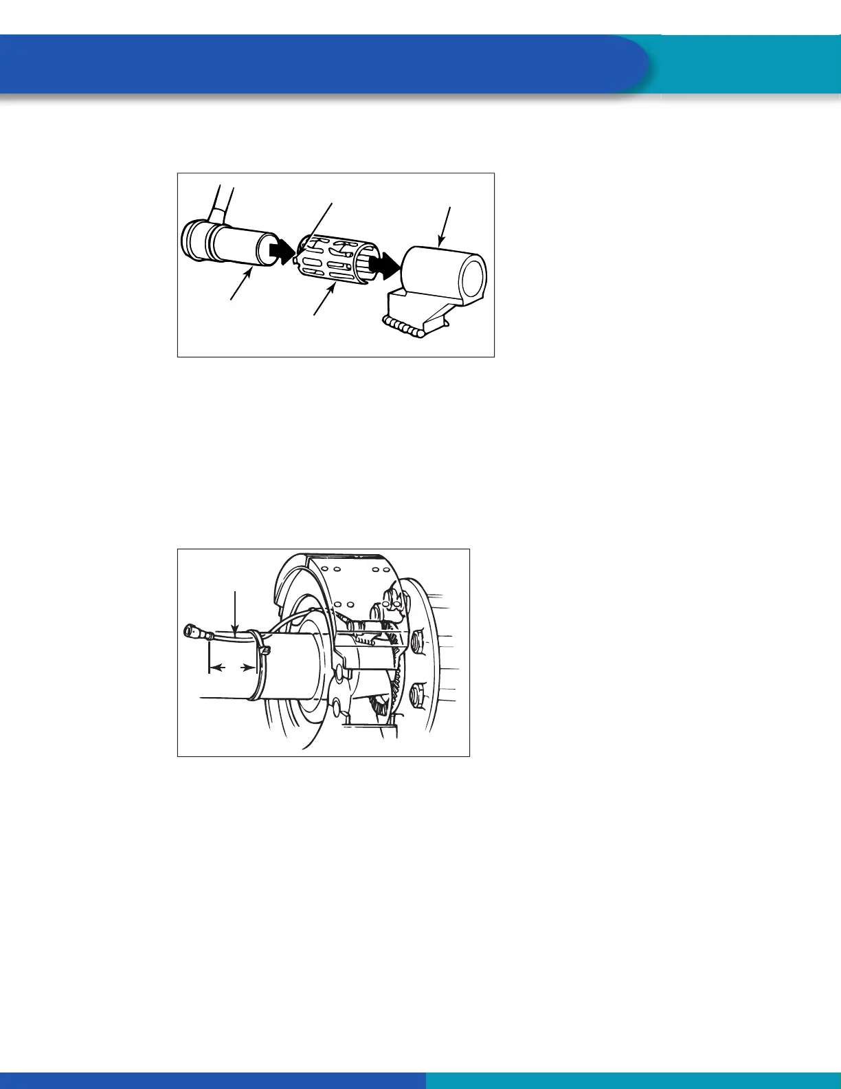
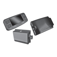
3. Push the spring clip into the sensor holder from the inboard side until the spring clip tabs are against
the sensor holder. Push the sensor into the spring clip as far as possible. Figure 29.
Fig. 29
SPRING
CLIP TAB
SENSOR
SPRING
CLIP
SENSOR
HOLDER
4003572a
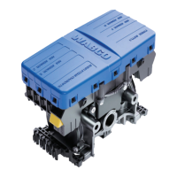
4. Route the sensor cable toward the brake chamber, over the brake spider or through the prestamped
hole dedicated for ABS sensors. Route to the back side of the axle. Secure the cable to the axle
between the brake spider and the suspension brackets. Continue to route the sensor cable behind the
spring seats. Secure the cable to the axle one inch from the molded sensor plug. Figure 30.
Do not overtighten tie wraps on a cable. Overtightening can damage the cable. Do not tie wrap the molded
sensor plug. The sensor extension cable must follow the brake hose to the ECU/valve assembly to allow for
axle jounce and rebound.
Brake hose clips with a provision for the sensor extension cable are recommended as opposed to tie
wraps. WABCO does not supply this part.
Fig. 30
SENSOR
CABLE
3"
(76 MM)
4003573a
5. Install the wheel hub carefully so that the tooth wheel pushes against the sensor as the wheel
bearings are adjusted. There should be no gap between the sensor and the tooth wheel. If the gap is
too large, this can cause the ECU to log a fault code.
6. Test the sensor output voltage. Use a volt/ohm meter to check the output voltage of the sensors while
rotating the wheel at approximately 1/2 revolution per second. Minimum output must be 0.2 volts AC,
though if the wheel is spun faster than 1/2 of a revolution per second, the reading will likely be higher.
It is important to spin the wheel at the correct speed to determine the output is in fact correct. If
minimum output is less than 0.2 volt AC, push the sensor toward the tooth wheel. Recheck the sensor
output.