Troubleshooting GP Repair
wc_tx000548gb.fm 104
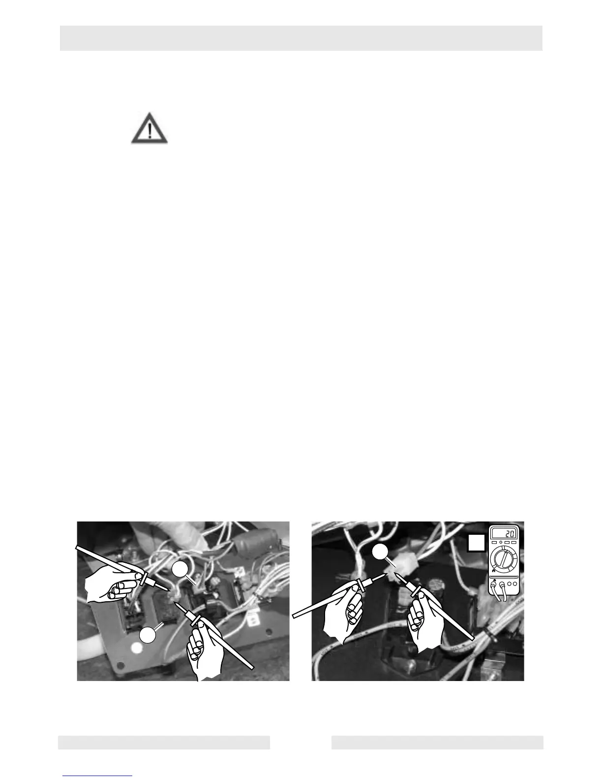
6.24 Checking Auto Idle Circuitry Between Fuse and Auto Idle Unit
See Graphic: wc_gr003132
Electric shock hazard. Only qualified personnel should conduct this
test.
Voltage may be prevented from reaching the idle solenoid by a faulty
auto idle switch or by a faulty auto idle unit. To check the circuit, carry
out the following procedure:
6.24.1 Stop the generator.
6.24.2 Remove the screws which secure the control panel to the generator.
Locate the auto idle switch (a).
6.24.3 Check the continuity of the auto idle switch.
• If the switch lacks continuity, replace it.
• If the switch has continuity, it should be functioning.
6.24.4 Remove the plug from the back of the auto idle unit (b).
6.24.5 Start the generator.
6.24.6 Check the voltage between the red and black wires of the plug. There
should be 20±2V. At this point in the troubleshooting, you should have
measured voltage at the fuse but not at the idle solenoid, and the auto
idle switch should have checked OK. Therefore:
• If voltage is measured to the auto idle unit but not at the idle sole-
noid, the auto idle unit is malfunctioning, replace it.
• If no voltage is measured at the auto idle unit, check the wiring
between the fuse and the auto idle unit. Repair or replace the wir-
ing as needed.
WARNIN