GP Repair Theory of Operation
wc_tx000547gb.fm 71
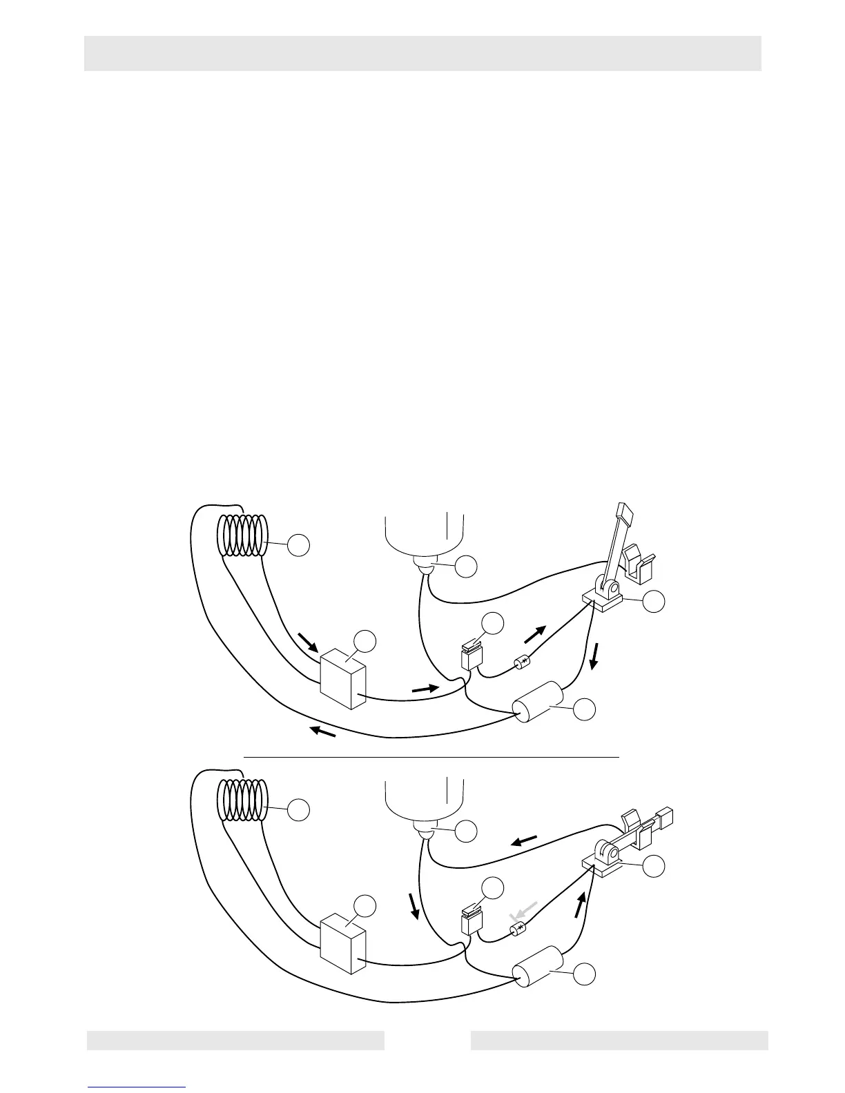
5.5 Anti-Afterfire Circuit
See Graphic: wc_gr003121
The anti-afterfire circuit consists of the DC winding (a), the rectifier (b),
one half of the engine ON/OFF switch (c) (shown as a simple switch
for this discussion), the 5A fuse (d), the anti-afterfire solenoid (AAS)
(e), and the 1000 microfarad capacitor (f).
When the engine is running, AC voltage is induced into the DC
winding—AC current flows to the rectifier. The AC voltage at the
rectifier is rectified into DC. This DC current flows to the engine ON/
OFF switch. With the engine ON/OFF switch in the ON position, power
is diverted from the AAS to the capacitor and back to the DC winding.
As current flows, the capacitor charges. When the engine ON/OFF
switch is placed in the OFF position, power is cut to the engine ignition
system and the engine stops running. As the engine stops revolving,
the voltage induced in the DC winding falls off. What voltage is
available is sent to the AAS through the engine ON/OFF switch. At the
same time, the capacitor discharges sending its stored DC voltage to
the AAS also through the engine ON/OFF switch. The AAS energizes
and cuts fuel flow to the engine’s carburetor.
a
c
DC
DC
DC
DC
AC
b
d
e
f
a
c
DC
DC
DC
DC
wc_gr003121
b
d
e
f