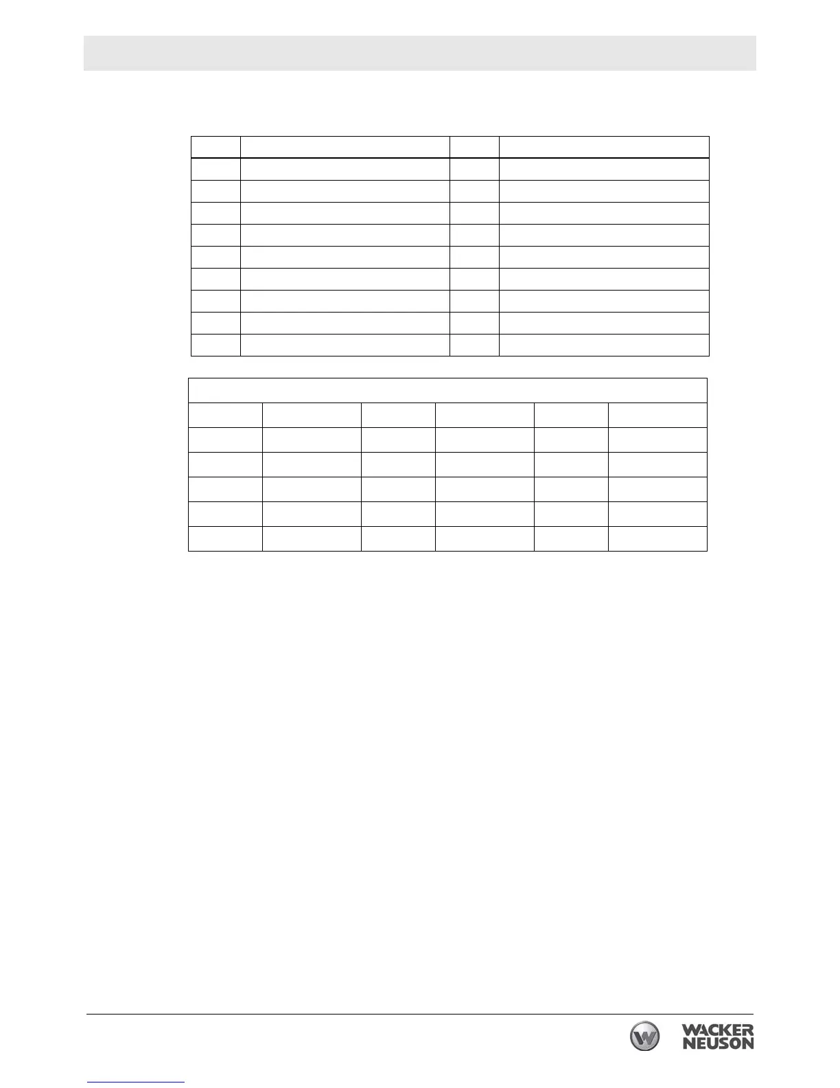
GPi 1700 Schematic
wc_tx001236gb.fm
43
4.1 Schematic Components
Component Component
A Engine K Inverter and engine control unit
B Control panel L DC circuit breaker
C Step motor M DC output terminal
D Ignition coil N Ground terminal
E Pickup coil O Engine switch
F Oil level sensor P Auto power save switch
G Main coil Q AC receptacle
H DC coil R Generator
J LED indicator
Wire Colors
Blk Black Brn Brown Org Orange
Blk/W Black/White Brn/W Brown/White Gry Gray
Blu Blue Grn Green R Red
LBlu Light Blue Grn/W Green/White W White
Y Yellow W/Blk White/Black Grn/Y Green/Yellow
Pur Purple
 Loading...