Schematics RD 12A
7 2
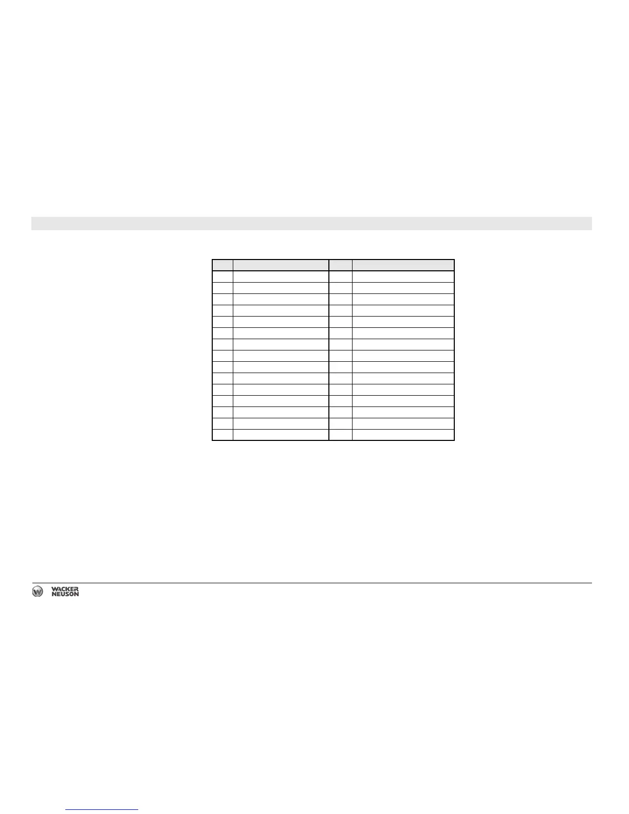
7.2 Electrical Schematic Components
Ref. Description Ref. Description
1 Work light switch 16 Rear light (optional)
2 Throttle switch 17 Left head light (optional)
3 Pump switch 18 Right head light (optional)
4 Key switch 19 To magneto kill
5 Vibration indicator light (green) 20 Crank relay
6 Low fuel indicator light (amber) 21 Neutral relay
7 Alternator (30A) 22 Spray bar pump
8 Starter solenoid 23 Fuel cutoff solenoid
9 Starter motor 24 Reverse switch
10 Battery 25 Vibration switch
11 Fuel level sensor 26 Neutral switch
12 Vibration solenoid (front) 27 Seat switch
13 Throttle solenoid 28 Strobe light (optional)
14 Pump timer module 29 Backup alarm (optional)
15 Hourmeter 30 Voltage regulator relay