10
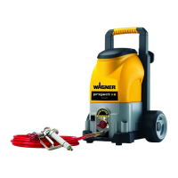
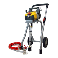
Wagner Project Pro 117 - 0418B
Assembly
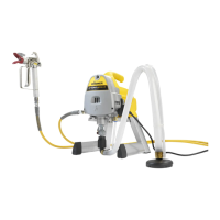
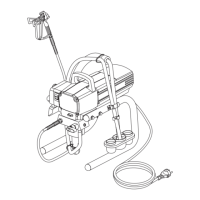
Figure 2 - Attaching the Hose
Make sure that the pump is switched o (position O) and
the spray device is disconnected from the power supply.
1. Thread the high pressure hose to the spray hose port. Tighten
with an adjustable wrench.
2. Thread the other end of the hose to the spray gun. Grip the
spray gun with an adjustable wrench on the handle, and
tighten the hose nut with the other.
The spray tip should not be attached until after the
sprayer and spray hose have been purged and primed.
Figure 3 - Attaching the Suction Set
1. Remove cap from inlet valve (a). Thread the suction tube onto
the inlet valve and tighten rmly by hand. Be sure that the
threads are straight so that the tting turns freely.
2. Push the return hose into the return connection piece.
Before You Begin
Preparation of the Coating Material
UsingProjectPro117interiorwallpaints,varnishesandglazescan
be applied by spraying without diluting them, or by diluting them
slightly.
Detailed information is available in the technical data sheet of the
manufacturer ( Internet download).
1. Stirthematerialthoroughlyanddiluteitinthecontaineras
per the recommended dilution (an agitator is recommended
for stirring).
Thinning recommendation
Sprayed material
Glazes undiluted
Wood preservatives containing
solvents or based on water, mordants,
oils, disinfection agents, plant
protective agents
undiluted
Paints containing solvents and
water-soluble paints, primers, vehicle
coating paints, thick-lm glazes
dilute by 5 - 10%
Interior wall paint (dispersions and latex
paint)
dilute by 0 - 10%
2. Do a test spray (e.g. on to a piece of cardboard).
If the paint sprays evenly, as shown in g. 11 A, all the
setting must be correct.
If the paint looks stripy after spraying, as shown in g.
11 B, gradually increase the pressure, or dilute more in
5% steps.
Figure 4 - Locking the Spray Gun
Always lock the trigger o when attaching the spray
tip or when the spray gun is not in use.
1. The gun is secured when the trigger lock is at a 90° angle
(perpendicular) to the trigger in either direction.
Figure 5 - Pressure Relief Procedure
Be sure to follow the Pressure Relief Procedure
when shutting the unit o for any purpose. This
procedure is used to relieve pressure from the spray
hose.
1. Lockthesprayguno.FliptheON/OFFswitchtotheOFF
position.
2. TurnthePRIME/SPRAYknobtoPRIME.
3. Unlockthespraygunandtriggerspraygunintothesideof
thematerialbucket.Lockthespraygun.
Priming
Figure 6 - Preparing to Prime
1. Sprayalittleoiloutoftheprovidedaskintothemarked
opening(tip:tiltthedeviceback).Lighthouseholdoilcanbe
substituted if necessary.
2. FullyinserttheQuicko™valvetomakesuretheinletballis
free.
Figure 7 - Priming the Sprayer
1. Place a full container of spraying material underneath the
suctiontube(a).Securethereturntube(b)intoawaste
container.
2. SlidethePressureTrac™tomaximumpressure(+).
3. TurnthePRIME/SPRAYknobtoPRIME.
4. PluginthesprayerandmovetheON/OFFswitchtotheON(l)
position.
The unit will begin to draw material up the suction
tube, into the pump, and out the return tube. Let the
unit cycle long enough to remove test uid from the
pump, or until spray material is coming from the return
tube.
5. SwitchthepumpOFF(O).Removethereturntubefromthe
waste container and place it in its operating position above
thecontainerofsprayingmaterial.Usethemetalcliptobind
the two hoses together.
Figure 8 - Priming the Spray Hose
1. UnlockthespraygunandturnthePRIME/SPRAYknobto
PRIME.
The spray tip should not be attached to your spray gun
when purging your spray hose.
2. PULLthetriggerandaimthespraygunatthesidewallofa
waste container. If using oil-based materials, the spray gun
must be grounded while purging (see warning below).
Field of application
Coating of interior walls as well as small and medium-sized objects
outdoors (e.g. garden fences, garage doors, etc.).
 Loading...