15
VERSION 06/2018
ORDER NUMBER DOC 2343275
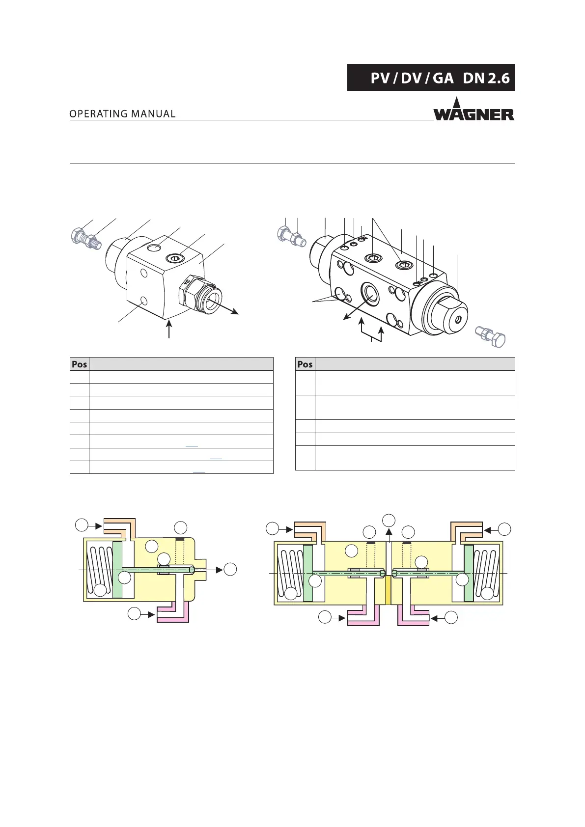
5 DESCRIPTION
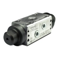
5.1 COMPONENTS
Single valves Double valves
B_04692
B
Q
D
K
E
A
C
O
P
B
D
L
K
K
A
O
P
A
C
K
E
Q
B_04690
B
L
Designation
A Clamping nut
B Control air connection
C Valve housing
D Product inlet
E Product outlet
G Valve rod (see Chapter 5.2)
H Pressure spring (see hapter 5.2)
I Set of seals (see hapter 5.2)
Designation
K Mounting holes/threads for valve block
mounting
L Leakage hole (PTFE valves) or connection for
separating agent supply (FFKM valves)
O Adjusting screw (for dosing valves only)
P Lock nut (for dosing valves only)
Q Product connection closed (open for circulation
operation)
5.2 MODE OF OPERATION
Single valves Double valves
B_04691
B
H
G
D
C
I
E
Q
B_04694
B
H
G
D
D
C
E
I
G
B
H
Q Q
– In the case of double valves, two valves are located in a valve housing (C).
– All valves are switched individually by means of the control air (B).
– The control piston positioned on the valve rod (G) in the valve's housing (C) is
pressurized and thus opens the passageway to the product outlet (E).
– Closing is eected by means of a pressure spring (H) after the control air pressure (B)
has dropped.
– The set of seals (I) prevents product from owing into the housing (C).
– Securing the valve: Remove the control air line from the control air connection (B).
 Loading...