Do you have a question about the WAGNER SUNGO S and is the answer not in the manual?
Solar circulation pump on/off controlled by temperature difference between collector and tank.
Solar circulation pump speed controlled via impulse packet control, adjustable 30-100%.
Measuring sensor for upper tank area, no switch function or diagnostics monitoring.
Display of minimum and maximum temperature values for sensors T1 and T2.
Allows manual switching of input and output channels; returns to automatic after 8 hours.
Sets a time lag for checking temperature values during manual operation.
Cools collector if tank temperature limit exceeded; pump switches off if T1 rises above standard value.
Reduces tank temperature to a preset lowest value, e.g., for vacations.
Enables solar heating system operation with sensor T1 in the collector connecting pipe.
System messages for interrupted or shorted-out sensors displayed with symbols and correction steps.
Electronic on/off switch for 230V outputs, consists of 2 diodes switched anti-parallel.
Stops solar charging if collector temperature exceeds set limit to protect system components.
Installation and commissioning must be by qualified installer; comply with national and local regulations.
Controlling solar thermal systems using applicable control patterns and additional functions.
Check suitability for purposes other than solar thermal systems; guarantee lapse if unsure.
Mains disconnection, external switch, temperature limits, display placement, and system integrity checks.
Instructions for opening the control casing and mounting the unit to the wall.
Affixing the unit to the bracket, opening cable ducts, and routing cables.
Rules for flexible wires, tinning/crimping wire ends, and using PG9 screws.
Connecting mains power via ON/OFF switch; unit designed for 230V AC/50Hz.
Guidelines for extending sensor wires, using shielded cable, and connecting without regard to polarity.
Spike protection on sensor terminals; T1 requires SP2 box with excess voltage protection.
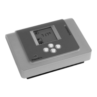
Explanation of display elements, symbols, and button functions for navigation and operation.
Displays current, minimum, and maximum balance values for collector temperature.
Displays current, minimum, and maximum balance values for lower tank temperature.
Displays the current temperature of the upper tank area (sensor T3).
Displays total operating hours and allows resetting them.
Function display showing pump idle (off) or active (on) based on temperature difference.
Sets the maximum temperature limit for the lower half of the tank.
Sets the temperature difference required to switch the solar circulation pump on.
Sets the temperature difference required to switch the solar circulation pump off.
Sets the minimum temperature for starting switch-on difference analysis.
Adjusts the set point for speed control based on temperature difference.
Sets the minimum speed percentage for the solar circulation pump.
Sets the maximum speed percentage for the solar circulation pump (SECUSOL).
Sets the charge time for SECUSOL systems at 100% pump speed.
Allows manual switching of the solar circulation pump (output A1) on or off.
Sets a lag time for manual operation mode returning to automatic mode.
Selects the operating mode: Standard single-tank or SECUSOL system.
Activates system protection and sets its start temperature.
Activates collector cooling and sets its start temperature.
Activates tank cooling and sets its switch-off temperature.
Activates vacuum tube collector function and sets run time/switch-on value.
Displays system messages with caution symbols for errors and their corrections.
Indicates sensor or line connection interruption/defunct and correction steps.
Indicates sensor short circuit and correction steps.
Indicates excessive temperature difference between collector and tank over 30 mins.
Table showing resistance values for Pt1000 sensors at different temperatures for checking condition.
Diagram and description of a standard single-tank solar heating system controlled by SUNGO S.
Diagram and description of the SECUSOL system controlled by SUNGO S.
| Brand | WAGNER |
|---|---|
| Model | SUNGO S |
| Category | Controller |
| Language | English |