EasyManua.ls Logo

WAGNER ProfiTech M User Manual

WAGNER ProfiTech M
108 pages
To Next Page IconTo Next Page
Page #1 background imageLoading...
Page #1 background image
II 3D Ex tc IIIB T60°C Dc
Pro Tech M
Hardware + Installation
Version 07 / 2014
Translation of the Original
Operating Manual

Table of Contents

Question and Answer IconNeed help?

Do you have a question about the WAGNER ProfiTech M and is the answer not in the manual?

WAGNER ProfiTech M Specifications

General IconGeneral
BrandWAGNER
ModelProfiTech M
CategoryController
LanguageEnglish

Summary

Hardware and Installation

GENERAL

Preface

Introduction to the operating manual and device usage guidelines.

Warnings, Notices, and Symbols

Explains hazard symbols and warning notices used in the manual.

Languages

Lists available languages for the operating manual.

Abbreviations

Provides a list of abbreviations used in the manual.

Terminology for the Purpose of this Manual

Defines key terms used throughout the manual for clarity.

CORRECT USE

Device Type and Type of Use

Specifies the device type and its intended application and usage.

Use in Potentially Explosive Areas

Outlines conditions for using the device in Zone 22 hazardous areas.

Safety Parameters and Processible Materials

Lists safety parameters and types of powders that can be processed.

Reasonably Foreseeable Misuse and Residual Risks

Describes potential misuse scenarios and remaining risks.

IDENTIFICATION

Explosion Protection Identification

Details explosion protection classifications for MCM Master Control and CPS I/O.

Type Plate Information

Information found on the device's type plate.

COMPONENT DESCRIPTION

Functional Description

Describes the functions controlled by the Profi Tech M controller.

Protective and Monitoring Equipment

Details the importance and handling of protective and monitoring equipment.

Scope of Delivery

Lists the items included in the standard equipment package.

MCM Controller Components Overview

Lists and describes the main components of the MCM controller.

CONTROL UNIT/SPRAY GUN COMPONENTS

Rack Components

Details the components included in the Rack, such as air distributor and base rack.

EPG-S2 Control Unit

Describes the EPG-S2 universal control unit and its spray gun compatibility.

EPG-Sprint X Control Unit

Describes the EPG-Sprint X universal control unit and its manual gun compatibility.

PULSE GENERATOR COMPONENTS

Encoder Unit

Describes the encoder unit and its specifications.

Bracket Set for Encoder

Lists the bracket set required for encoder installation.

Connection Cable for Encoder

Details the connection cable for the encoder.

LIGHT GRID SET LGS 25 COMPONENTS

LGS 25 Light Grid Set

Describes the LGS 25 light grid set, including its components.

KONTUR 2 LIGHT CURTAIN COMPONENTS

Kontur 2 Light Curtains

Lists Kontur 2 light curtains by length, resolution, and order number.

Light Curtain Connection Cables

Lists connection cables for Kontur 2 light curtains.

LIGHT CURTAIN CML720I COMPONENTS (FROM 06/2014)

CML720i Light Curtain Modules

Lists CML720i light curtain modules by type, length, beam spacing, and order number.

Y Connection Cables for CML720i

Lists Y connection cables for CML720i light curtains and their uses.

Assembly Material for CML720i

Lists assembly materials for CML720i light curtains, including swivel mounts.

MOTION EQUIPMENT COMPONENTS

VU1 Reciprocator

Describes the VU1 reciprocator and its specifications for automatic coating systems.

HU1 Sliding Table

Describes the HU1 sliding table for positioning reciprocators.

Protection Door Components

Lists components related to the protection door module.

MISCELLANEOUS

Small Components for Assembly

Lists small, system-dependent components for mechanical and electrical assembly.

Grounding Cable for Potential Equalization

Details the grounding cable for potential equalization.

TECHNICAL DATA

MCM Master Control Technical Data

Detailed technical specifications for the MCM Master Control.

COMPRESSED AIR QUALITY

Compressed Air Quality and Accessories

Details compressed air quality requirements and related accessories.

OPERATING ELEMENTS ON THE MASTER MODULE

PC Controller and Emergency Stop

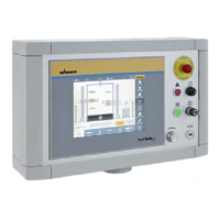
Describes the PC controller screen and the emergency stop button.

Display and System Release Controls

Details the "Fault" display, "System release" display, and key switch.

Rotary Controller and USB Connection

Explains the rotary controller and USB connection for memory media.

DISPLAY ELEMENTS FRONT SIDE OF EPG S2

LED Displays: Operating Voltage and CAN Communication

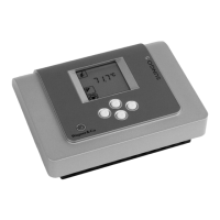
Explains the LEDs for Operating Voltage and CAN Data Communication.

LED Displays: Release, Air, and High-voltage

Describes the LEDs for Release, Air, and High-voltage status.

LED Display: Warning/Malfunction

Explains the LED indicating warnings or malfunctions.

ASSEMBLY AND COMMISSIONING

Training for Assembly Staff

Emphasizes the need for trained staff for assembly and operation.

Storage Conditions

Specifies the required dry and dust-free conditions for storing components.

Installation Conditions

Outlines temperature and humidity requirements for installation.

Assembly Procedure for Profi Tech M Components

Setting Up the Rack

CPS Control Cabinet Design

Terminal Descriptions: Light Barriers and Emergency Stop

Terminal Descriptions: Powder Center and Booth Control

Terminal Block X30: Motion Technique and EPG-S2 Supply

CAN Addresses for MCM System

CONNECTING THE MCM MODULE

Connecting the MCM Module

Shows the MCM Master Control and CPS I/O Control modules with their connection cable.

Connections on MCM Master Control

Connections on MCM CPS I/O Control

Cable Entry on MCM CPS I/O Control

Connection Point for CAN Bus, EPG-Sprint X, and Encoder

CONNECTIONS IN THE RACK

Connections within the Rack

Illustrates connections for spray guns, ground wire, and supply voltage within the rack.

CONNECTING THE AUTOMATIC SPRAY GUNS ON THE EPG S2

Connecting Automatic Spray Guns to EPG S2

Diagram showing connections for Tribo and Corona spray guns on the EPG S2.

CONNECTING THE MANUAL GUNS TO THE EPG-SPRINT X

Connecting Manual Guns to EPG-SPRINT X

Diagram showing connections for manual guns to the EPG-SPRINT X.

Signals on the EPG-SPRINT X

Parameter Setting on the EPG-SPRINT X

POWER SUPPLY OF THE EPG CONTROL UNITS

Power Supply for EPG Control Units

Shows how to connect power supply to EPG S2 and EPG Sprint X units.

CONNECTING THE CONVEYOR ENCODER

Connecting the Conveyor Encoder

Details the connection of the conveyor encoder using a specific cable.

CONNECTING THE LIGHT CURTAINS

Connection Diagram for 'Kontur 2' Light Curtains

Illustrates the wiring diagram for connecting Kontur 2 light curtains.

Light Curtain Power and CAN Bus Connections

INSTALLATION OF THE "KONTUR 2" LIGHT CURTAINS

Installation of Kontur 2 Light Curtains

Provides installation notices and steps for Kontur 2 light curtains.

Grounding Light Curtains

CONNECTION DIAGRAM FOR LGS LIGHT GRID

Connection Diagram for LGS Light Grid

Shows the wiring diagram for connecting the LGS light grid sender and receiver.

ASSEMBLY OF CML720I LIGHT CURTAINS

Assembly of CML720i Light Curtains

Provides assembly notes and steps for CML720i light curtains.

Fastening Using Swivel Mount

CONNECTION DIAGRAM FOR CML720I LIGHT CURTAINS WITH CODE CATCHING

Connection Diagram for CML720i with Code Catching

Shows CAN cabling and 24 VDC connections for CML720i with code catching.

CONNECTION DIAGRAM FOR CML720I LIGHT CURTAINS WITHOUT CODE CATCHING

Connection Diagram for CML720i without Code Catching

Illustrates the wiring connections for CML720i without code catching.

CONNECTION DIAGRAM FOR CML720I HEIGHT LIGHT CURTAINS

Connection Diagram for CML720i Height Light Curtains

Illustrates the wiring connections for CML720i height light curtains.

GROUNDING OF CML720I LIGHT CURTAINS

Grounding of CML720i Light Curtains

Details the grounding requirements for CML720i light curtain components.

COMMISSIONING THE CML720I LIGHT CURTAINS

Light Curtain Lock Function

Explains the lock function to prevent incorrect adjustments and how to deactivate it.

Function Keys and Receiver LEDs

Describes function keys and LED indicators on the light curtain receiver display.

Receiver LED Status and Descriptions

Transmitter LED Status and Descriptions

Meaning of Display Symbols

SETTING THE BAUD RATE

Setting the Baud Rate

Step-by-step guide to setting the baud rate to 250 kBaud for light curtains.

SETTING NODE ID

Setting Node ID for CML720i Light Curtains

Assigns CANopen Node IDs to different CML720i light curtain configurations.

ALIGNMENT OPERATION

Light Curtain Alignment Procedure

Explains how to activate and perform the alignment operation for light curtains.

Alignment Status and Finalizing Alignment

CONNECTION OF MOTION TECHNIQUE

Connecting Motion Technique Components

Details connecting reciprocators and sliding tables to the Profi Tech M system.

CONNECTIONS WITH TWO MOTION UNITS

Connections for Two Motion Units

Illustrates the connection diagram for two motion units with the CPS.

CONNECTIONS WITH FOUR MOTION UNITS

Connections for Four Motion Units

Illustrates the connection diagram for four motion units with the CPS.

SETTING NODE ID'S AND BAUD RATE ON SLIDING TABLE

Setting Node ID and Baud Rate on Sliding Table

Guides on setting Node ID and Baud Rate via DIP switches on sliding tables.

SETTING NODE ID AND BAUD RATE ON RECIPROCATOR

Setting Node ID and Baud Rate on Reciprocator

Guides on setting Node ID and Baud Rate via DIP switches on reciprocators.

CONNECTING SPRAY GUN BLOW OUT FIXTURE

Connecting Spray Gun Blow Out Fixture

Details the connection of the spray gun blow out fixture to the HU1 sliding table.

GROUNDING

Grounding Importance and Risks

Explains the critical importance of grounding and associated risks of inadequate grounding.

Prerequisites for Perfect Grounding

Lists requirements for achieving proper grounding and coating quality.

Protective Clothing and Grounding Sparks

COMMISSIONING

Commissioning Steps and Checks

Outlines the steps for performing commissioning and system checks.

OPERATION

Training the Operating Staff

Emphasizes the necessity of qualified and trained operating staff.

General Safety Instructions for Operation

Provides essential safety rules and precautions for operating the system.

Work Procedures and Coating Operation

CLEANING AND MAINTENANCE

Cleaning Staff and Hazards

Identifies cleaning staff responsibilities and hazards associated with cleaning.

Safety Instructions for Cleaning

Outlines critical safety precautions to be followed during cleaning.

Cleaning Procedures and Intervals

Maintenance Staff and Safety Instructions

Incorrect Maintenance/Repair Warning

Safety Checks: Grounding Check

Maintenance Procedures and Intervals

INSPECTIONS ACCORDING TO DIN EN 50177: 2010

Technical Ventilation Effectiveness Checks

Details checks for technical ventilation effectiveness and interlocking.

High-Voltage Area Inspections

Covers inspections of parts carrying high-voltage outside the spray area.

Grounding Measures Effectiveness

Grounding of Work Piece Locating Points

Measures for Insufficiently Grounded Work Pieces

Fire Extinguishing Systems Effectiveness

DISASSEMBLY AND DISPOSAL

Disassembly Procedures and Safety

Provides warnings and steps for safe disassembly of the system.

SPARE PARTS

Ordering Spare Parts

Explains the information required for ordering spare parts correctly.

Maintenance and Repair Warnings

Warns against incorrect maintenance/repair and specifies authorized personnel.

Spare Parts Recommendation for Control Cabinet

EXTENDED OPERATING MANUALS

WARRANTY AND CONFORMITY DECLARATIONS

Important Notes Regarding Product Liability

Outlines manufacturer liability based on EC regulations.

Warranty Claim Procedures

Details the process and conditions for making a warranty claim.

CE Declaration of Conformity

Related product manuals