Maintenance Instructions REPLACING/REPAIRING
64
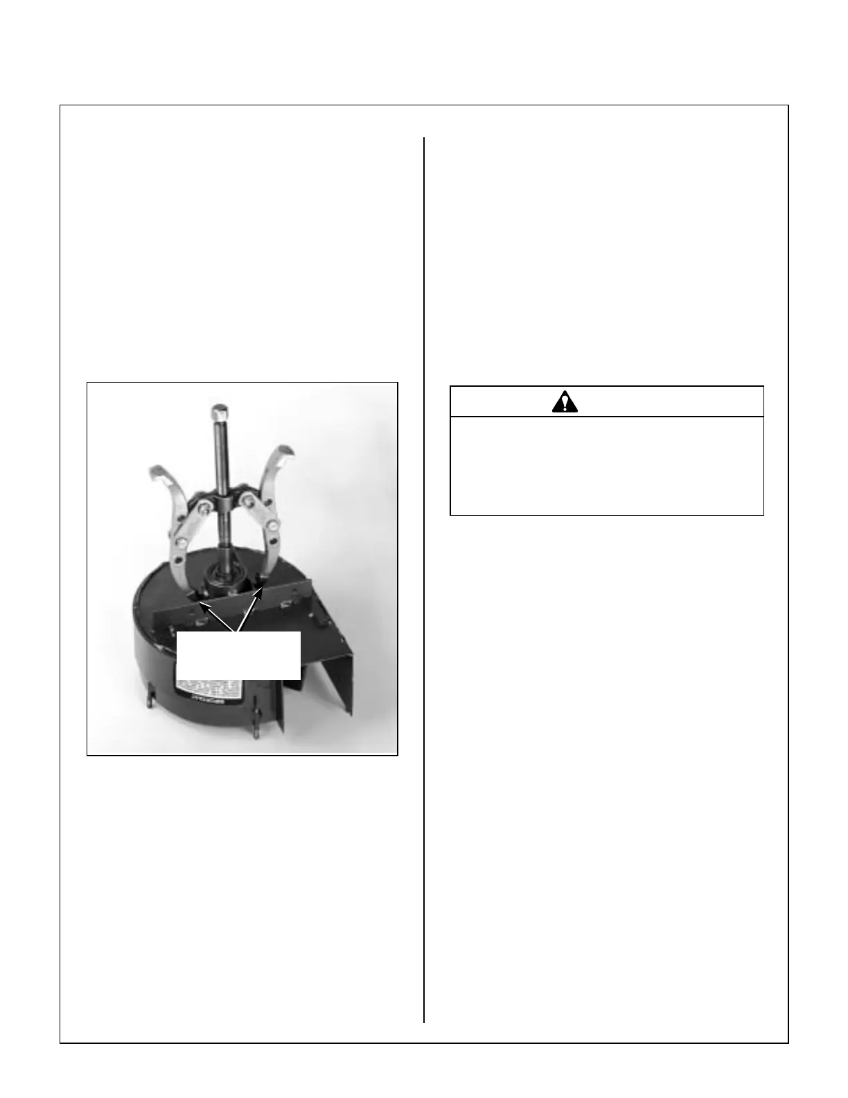
3. Press blower wheel out of the housing using a
wheel puller hooked to lugs on the bearing hous-
ing. The bearings have been secured in the
housing with a retaining compound - Loctite
®
RC/680, and considerable force will be re-
quired to break this bond. After the bearings
have “broken loose” from the housing, only light
pressure should be required to remove the
wheel assembly out of the housing.
NOTE: It may or may not be possible to remove
the front bearing from the blower wheel without
damaging it. If the bearing is damaged, it will
need to be replaced along with the wheel.
Pressing Blower Wheel Out of Housing
Blower Wheel Installation
1. To install the blower wheel, reverse the removal
procedures. The front bearing is mounted on
the blower wheel shaft, secured by a locking
collar. Drive the locking collar clockwise with a
punch, and tighten the set screw.
2. Press blower wheel and front bearing into the
blower housing. Use Loctite
®
RC/680 retaining
compound on the outer bearing race and inside
the bearing housing.
3. Press the rear bearing into place, using Loctite
®
on both the outer bearing race and the housing.
4. Install the locking collar on the rear bearing and
install the blower pulley to complete the blower
assembly. Torque the blower pulley set screws
to 250 in-lb (28.3 N
⋅m).
GHS Blower Assembly Installation
Reinstall the blower assembly into the mower using
the reverse procedures of GHS Blower Assembly
Removal.
ADJUSTMENTS
Safety Switches
There are four (4) safety interlock switches (and one
control switch if GHS equipped) on the tractor. Use
the panel nuts on the switch body to position each
switch for proper activation of the switch. The ad-
justment procedure for each switch is:
Seat Switch
Adjust switch position in body panel to achieve a
1/32 to 1/16 in. (.79 mm to 1.59 mm) air gap between
the switch plunger and seat frame with no weight on
the seat. Test for proper operation.
Wheel Puller
Hooked to Lugs on
Bearing Housing
DANGER
If the engine must be running to perform
a maintenance adjustment, keep hands,
feet, and clothing from moving parts. DO
NOT wear jewelry or loose clothing.