20
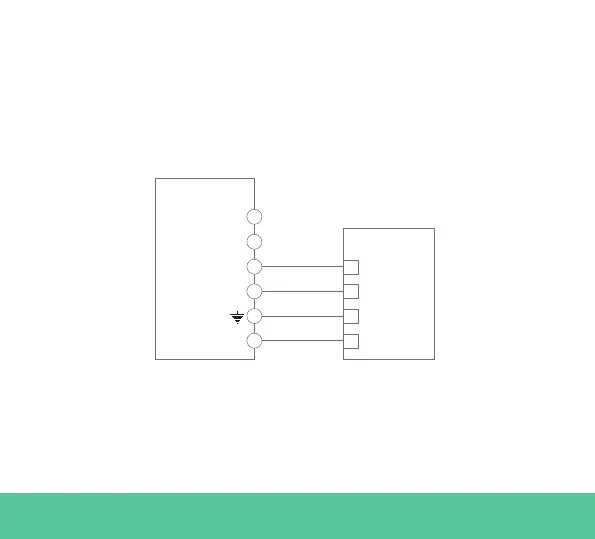
Fig. A2.2: Cabling in Temco energy meter
Fig. A2.2 shows the cabling between the energy meter and the Wallbox.
The numbers are refering to the Fig. A2.1. Before turning on the system
it is important to check again that the connection of “GND” and “12 V”
has been done correctly.
TEMCO
D- (RS485B)
RS485 +
RS485 -
Voltage -
Voltage +
GND
12 VPower +
D+ (RS485A)
Power
3
2
1
6
5
4
Wallbox
In the following pages Fig. A2.3, Fig. A2.4, Fig. A2.5 and Fig. A2.6 show
where to connect the cabling to the Wallbox.