Do you have a question about the Wallbox Commander 2 and is the answer not in the manual?
Refer to the charger's Installation Guide for proper installation procedures.
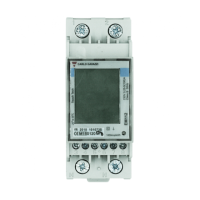
Only energy meters supplied by Wallbox are compatible for use.
Installation must be performed by qualified personnel according to local regulations.
Details on the number of primary/secondary chargers and energy meters.
Information on communication protocols between chargers and meters.
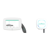
Lists the different Wallbox devices involved in the installation.
Details the tools needed for the setup and connection process.
Procedure to power off and open connected chargers for existing installations.
Steps for installing the charging network as per the manual.
Steps to power off and open only the primary charger for power sharing.
Instructions for performing steps within the Cabling network section.
Refer to the Power Sharing Smart Manual for additional details.
Setting up chargers in a chain and defining roles (T/NT).
Steps for installing the energy meter and primary charger.
Connecting secondary chargers and wiring the meter to the primary.
Diagram illustrating the placement of the energy meter within the electrical system.
Wiring diagram for connecting the Commander 2 with an energy meter.
Introduction to the EM 112 energy meter model.
Introduction to the EM 330 energy meter model.
Introduction to the EM 340 energy meter model.
Usage instructions for the SPM1-100-AC for 1-Phase installations up to 100A.
How to clip the SPM1-100-AC power meter onto the mains power cable.
Important note regarding the neutral cable and clamp usage.
Diagram showing electrical connections between SPM1-100-AC and Wallbox.
Copper, Commander 2, Pulsar Plus have two slots for cabling.
Details for making a T connection in the cabling network.
Details for making an NT connection in the cabling network.
Diagram for connecting Commander 2 chargers in a network.
Diagram showing the secondary-only connection for the Pulsar charger.
Overview of network composition: one primary and up to 24 secondary chargers.
How to use the rotary switch to set charger roles (Primary/Secondary).
Instructions for configuring chargers as standalone units.
Configure dynamic power sharing functionality on the Primary charger first.
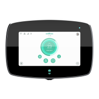
Primary charger can be configured via Wallbox app or touchscreen.
Standard/Business account needed; chargers stay unconfigured until Primary is set.
Input the total number of chargers in the network.
Configure max phase, min charger, and mains breaker current limits.
Navigating the configuration menu on the Commander touchscreen.
Using the Commander 2 touchscreen for configuration settings.
Primary chargers can be configured using the Wallbox mobile application.
Steps to access Configuration Menu and Dynamic Power Sharing via the app.
List of country-specific phone numbers for customer support.
Website and email for additional online assistance.
| Cable color | Black |
|---|---|
| Housing color | White |
| Mounting type | Wall |
| Built-in display | Yes |
| Display diagonal | 7 \ |
| Housing material | - |
| Socket type | Type 2 |
| Sockets quantity | 1 |
| Power source type | AC |
| Quantity per pack | 1 pc(s) |
| IEC protection class | III |
| Cross-section connection | 5 x 10 mm² |
| Mechanical impact protection code | IK10 |
| International Protection (IP) code | IP54 |
| Number of phases | 3 |
| Nominal frequency | 60 Hz |
| Three-phase output voltage supported | 400 V |
| Maximum operating power (three-phase) | 22 kW |
| Maximum operating current (three-phase) | 32 A |
| Sustainability certificates | CE |
| Storage temperature (T-T) | -40 - 70 °C |
| Operating temperature (T-T) | -25 - 40 °C |
| Depth | 115 mm |
|---|---|
| Width | 221 mm |
| Height | 152 mm |
| Weight | 2400 g |
| Charging cable length | 5 m |