5.4. Connect the Input and Output Cables
The control unit has input and output sockets in the lower panel of the unit.
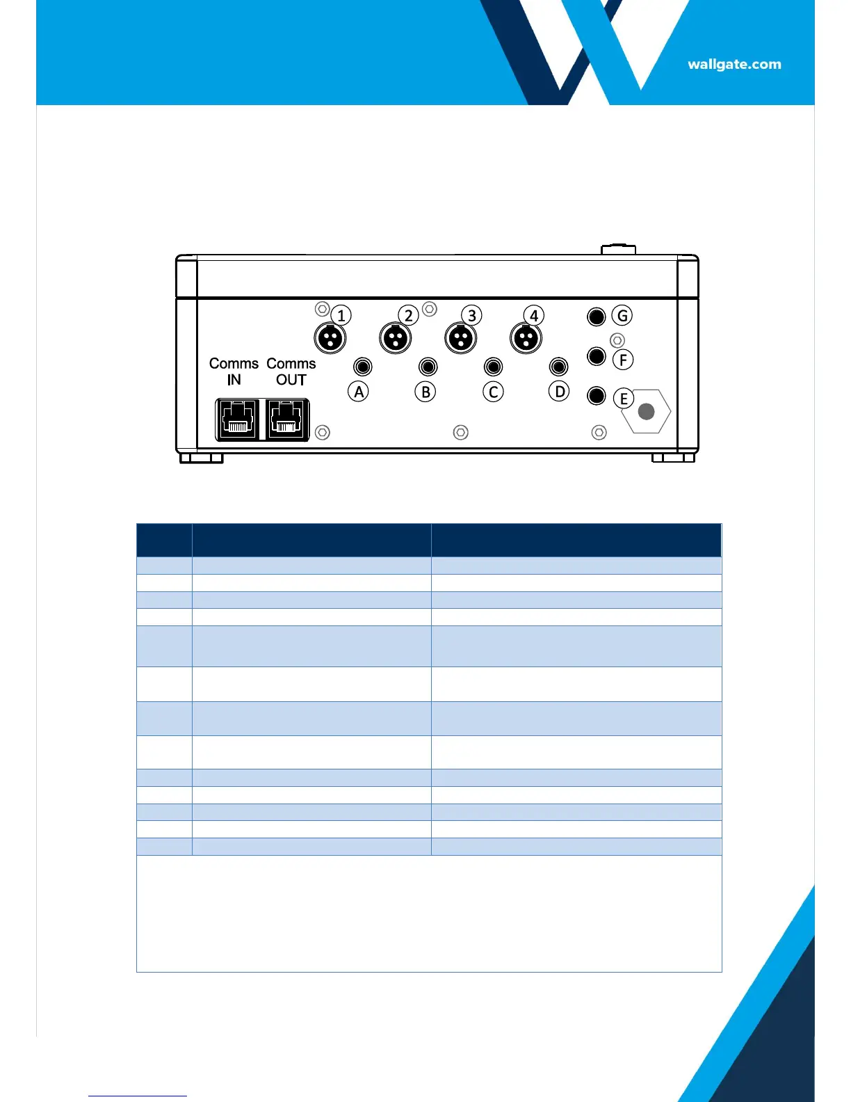
Refer to Figure 2 for the illustration of the lower panel.
Figure 2.Connectors in the WDC100 control unit
Output to Basin or bath Valve Cold
Opens Basin/bath Valve Cold
Output to Basin or bath Valve Hot
Opens Basin/bath Valve Hot
Input from WC Flush Piezo touch
button
User input (Piezo button or IR sensor) for
WC Flush
Input from Shower Piezo touch
button
User input (Piezo button or IR sensor) for
Shower
Input from Basin or bath Cold
touch button
User input (Piezo button or IR sensor) for
Basin/bath Cold
Input from Basin or bath Hot
touch button
User input (Piezo button or IR sensor) for
Basin/bath Hot
Auxiliary input set to Remote L.O.
Auxiliary input set to Remote Flush
Auxiliary input set to Half Flush
Auxiliary Inputs, E, F, and G are used when it is necessary to:
Lockout or disable the basin/bath, shower and WC from a remote switch.
Remotely flush the WC pan.
Activate a reduced flush for the WC pan with an additional touch button or IR sensor.
Clear lock outs.
Purge.
Connect a hygiene purge water flow sensor.
Table 2. Legend for Figure 2